Short stroke control valve

Active Publication Date: 2010-12-02
CONTROL COMPONENTS INC
View PDF8 Cites 15 Cited by
  • Summary
  • Abstract
  • Description
  • Claims
  • Application Information

AI Technical Summary

Benefits of technology

[0010]In the short stroke control valve of the present invention, the disk stacks or cages each feature labyrinth grooves and seals to reduce the leakage flow pass the plug and to reduce the effects of multiple clearance flows. Additionally, depending on the need for low end throttling, the number of labyrinth grooves within each of the cages may be different between stages. Further, the Cv in each of the disk stacks or cages may be varied to result in an overall custom characteristic curve for the val

Problems solved by technology

However, in some applications and valve designs, there is a limitation in the maximum allowable stroke due to space or design constraints.
Such design constraints may b

Method used


Image

  • Short stroke control valve
  • Short stroke control valve
  • Short stroke control valve

Examples


Embodiment Construction

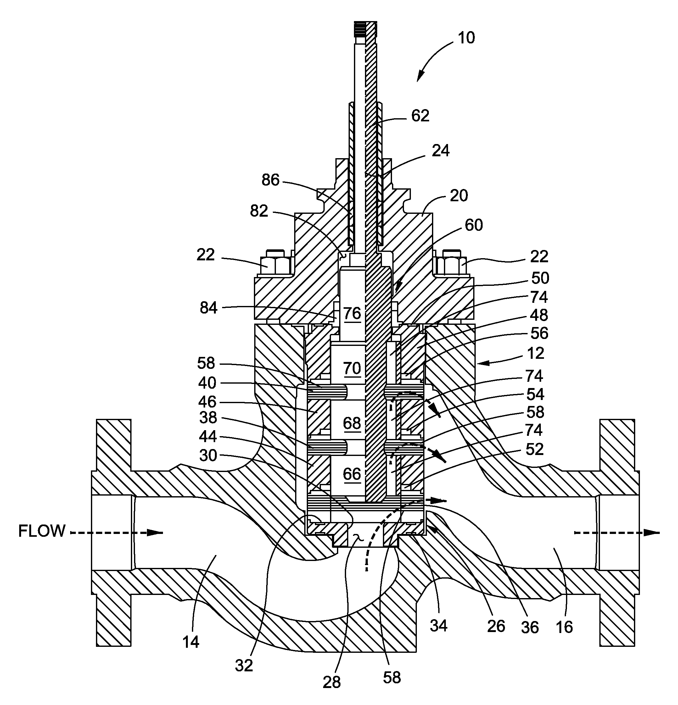
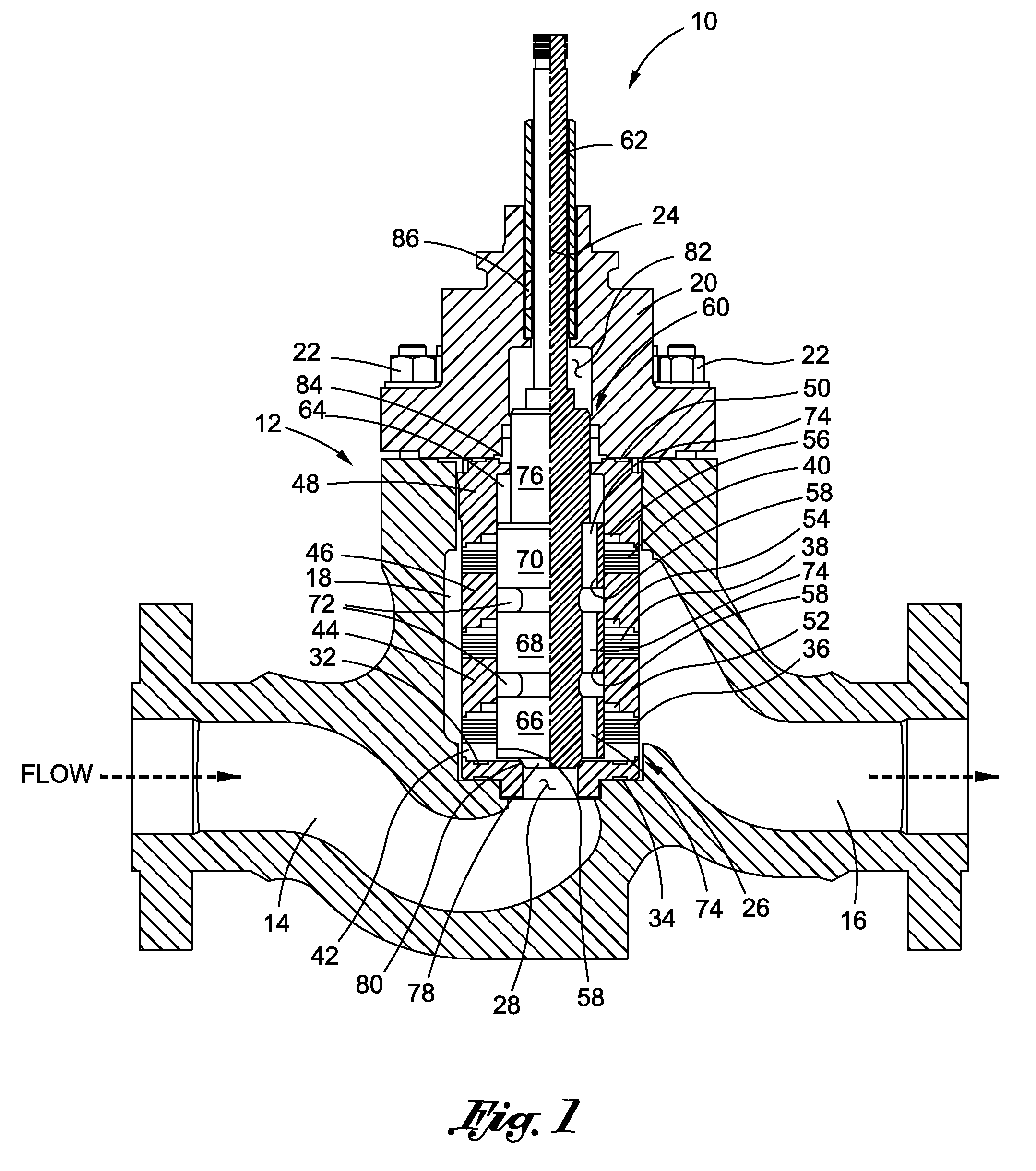
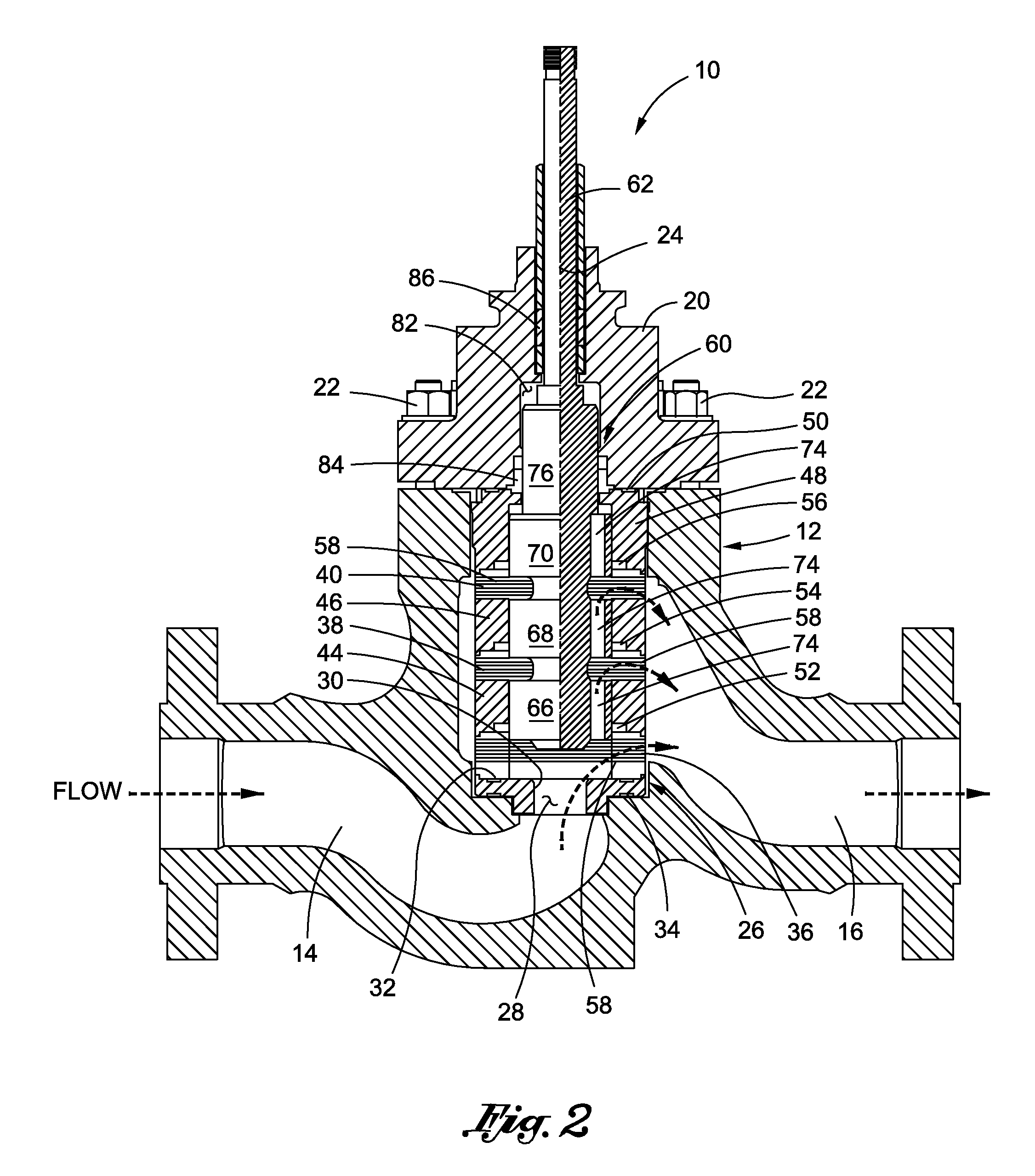
[0016]Referring now to the drawings wherein the showings are for purposes of illustrating a preferred embodiment of the present invention only, and not for purposes of limiting the same, FIGS. 1 and 2 are cross-sectional views of a short stroke control valve 10 constructed in accordance with the present invention. As will be described in more detail below, the valve 10 is shown in FIG. 1 in a closed or shut-off position, and is shown in FIG. 2 in an open position which allows for the flow of a fluid therethrough.

[0017]The valve 10 comprises a valve body 12 which defines an inflow passage 14 and an outflow passage 16. The inflow and outflow passages 14, 16 each fluidly communicate with an interior chamber or valve gallery 18 defined by the body 12. In addition to the body 12, the valve 10 includes a bonnet 20 which is attached to the body 12 and partially encloses the gallery 18. As seen in FIGS. 1 and 2, the attachment of the bonnet 20 to the body 12 is preferably facilitated throug...


PUM


Abstract

A short stroke flow control device or valve which is adapted to provide velocity control trim in a short stroke. The valve constructed in accordance with the present invention comprises multiple disk stacks or cages which are separated from each other by intervening spacers, and are placed axially in a valve gallery clamped between a seat ring and bonnet of the valve. The fluid passageways in the cages are throttled in a controlled manner by a plug which defines multiple throttling elements or plug lobes, the number of plug lobes defined by the plug preferably being equal to the number of cages included in the valve. The plug lobes of the plug control the flow of fluid through the disk stacks or cages in tandem. All of the throttling elements or plug lobes of the plug, with the possible exception of the plug lobe which contacts the seat ring for closure, is larger in diameter than the remainder of the plug and has at least one kidney bean shaped flow passage extending therethrough. The flow area of such flow passages in the plug lobes is designed to satisfy prescribed seat bore velocity criteria.

Description

CROSS-REFERENCE TO RELATED APPLICATIONS[0001]Not ApplicableSTATEMENT RE: FEDERALLY SPONSORED RESEARCH / DEVELOPMENT[0002]Not ApplicableBACKGROUND OF THE INVENTION[0003]1. Technical Field of the Invention[0004]The present invention relates generally to flow control devices and, more particularly, to a uniquely configured control valve which is adapted to provide velocity control trim in a short stroke to accommodate space or design constraints.[0005]2. Description of the Related Art[0006]There is currently known in the prior art control valves which include stems and plugs that are linearly displaced during normal operation of the valve. Within these valves, which are often referred to as linear displacement valves, the plug is disposed and moveable within a disk stack or valve cage which defines a multiplicity of tortuous and / or non-tortuous fluid passageways. Certain linear displacement valves are configured for “over plug flow” wherein fluid flows radially inward into the interior o...

Claims


Application Information

Patent Timeline
IPC IPC(8): F16K3/00
CPCF16K47/08F16K3/267Y10T137/86734Y10T137/86767Y10T137/8741
Inventor SAMY, SEKHAR
Owner CONTROL COMPONENTS INC
Why Eureka
Try Eureka