Riser pipe with adjustable auxiliary lines

a technology of auxiliary lines and riser pipes, which is applied in the direction of hose connections, drilling pipes, mechanical equipment, etc., can solve the problems of affecting the longitudinal mechanical strength of the structure consisting of the entire riser, the dead weight of the auxiliary lines is very penal, and the welds performed between the connecting means and the tubes are not suitable for high-pressure circulation effluent coming from the well or the surfa

Inactive Publication Date: 2010-12-02
INST FR DU PETROLE
View PDF16 Cites 61 Cited by
  • Summary
  • Abstract
  • Description
  • Claims
  • Application Information

AI Technical Summary

Problems solved by technology

Owing to these elements mounted sliding into one another, the lines intended to allow high-pressure circulation of an effluent coming from the well or from the surface cannot take part in the longitudinal mechanical strength of the structure consisting of the entire riser.
Now, in the perspective of drilling at water depths that can reach 3500 m or more, the dead weight of the auxiliary lines becomes very penalizing.
Furthermore, the welds performed between the connecting means and the tubes can increase the length difference between the various tubes of a riser section.
The offsets in the axial position of the connectors, due to the length differences of the tubes, can make connection impossible.

Method used


Image

  • Riser pipe with adjustable auxiliary lines
  • Riser pipe with adjustable auxiliary lines
  • Riser pipe with adjustable auxiliary lines

Examples


Embodiment Construction

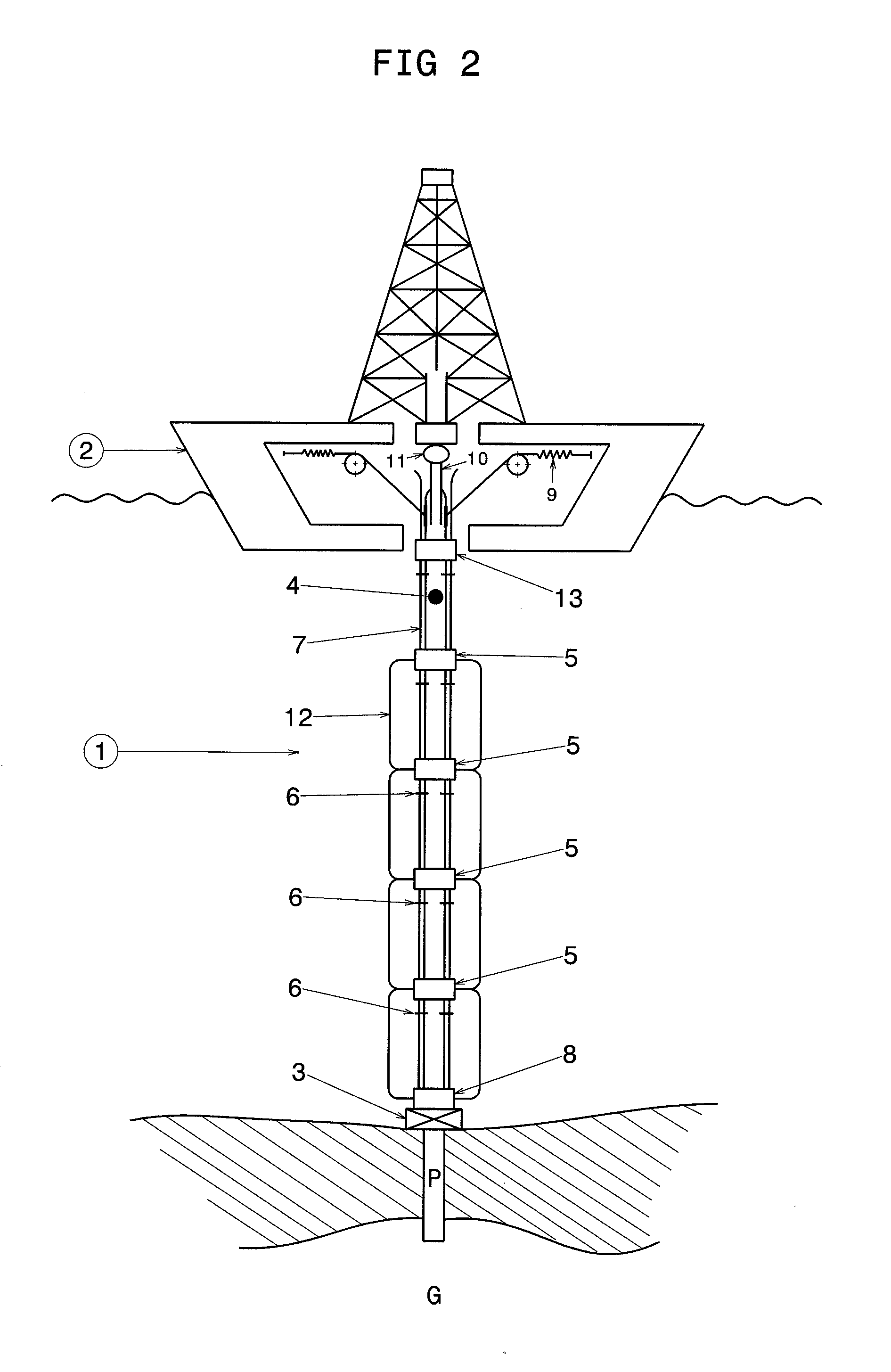
[0026]FIG. 2 diagrammatically shows a riser 1 installed at sea, intended for drilling a well P for development of reservoir G. Riser 1 forms an extension of well P and it extends from wellhead 3 to floater 2, a floating platform, a barge or a vessel for example. Wellhead 3 is provided with preventers commonly referred to as “BOPs” or “Blow-Out Preventers”.

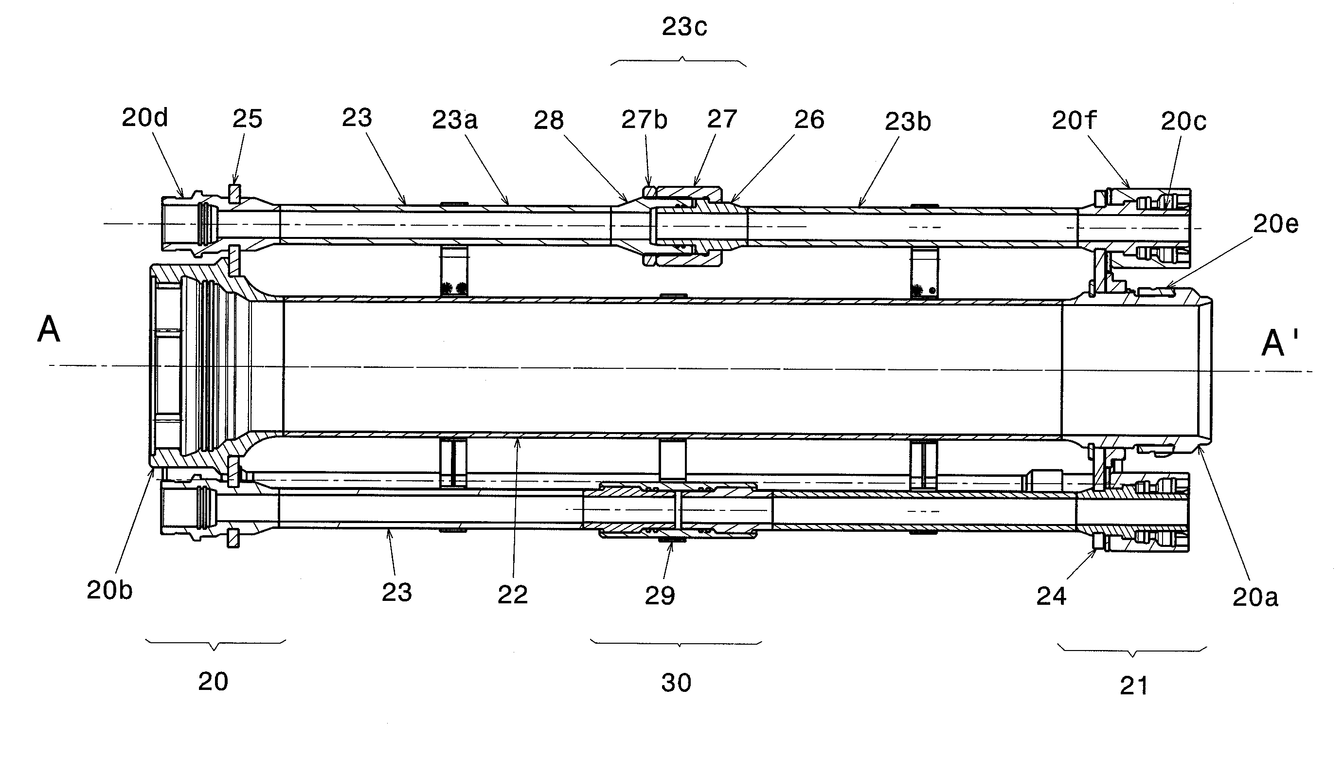
[0027]The riser diagrammatically shown in FIG. 2 comprises a main tube 4 and auxiliary lines 7.

[0028]With reference to FIG. 2, auxiliary lines 7 are arranged parallel to and on the periphery of main tube 4 consisting of the assembly of tubes. The auxiliary lines referred to as kill line and choke line are used for circulating fluids between the well and the surface, or vice versa, when the BOPs are closed notably in order to allow control procedures relative to the inflow of fluids under pressure in the well. The auxiliary line referred to as booster line allows mud to be injected at the bottom of the riser. The auxiliary line(s) r...


PUM


Abstract

The riser pipe section comprises a main tube 22 and auxiliary line elements 23 arranged parallel to tube 22. The ends of the main tube comprise connectors 20a and 20b allowing longitudinal stresses to be transmitted. The ends of auxiliary line elements 23 comprise connectors 20c and 20d. Auxiliary line elements 23 consist of two parts 23a and 23b assembled by an adjustment device 23c or 30 allowing the axial length of each auxiliary line element to be adjusted.

Description

FIELD OF THE INVENTION[0001]The present invention relates to the field of very deep sea drilling and oil reservoir development. It concerns a riser pipe element comprising at least one line, or rigid auxiliary line, which can transmit tensional stresses between the top and the bottom of the riser.BACKGROUND OF THE INVENTION[0002]A drilling riser is made up of an assembly of tubular elements whose length generally ranges between 15 and 25 m, assembled by connectors. The weight of the riser borne by an offshore platform can be very great, which requires suspension means of very high capacity at the surface and suitable dimensions for the main tube and the connection fittings.[0003]So far, the auxiliary lines: kill lines, choke lines, booster lines and hydraulic lines are arranged around the main tube and they comprise insertable fittings fastened to the riser element connectors in such a way that these high-pressure lines can allow a longitudinal relative displacement between two succ...

Claims


Application Information

Patent Timeline
Patent Type & Authority Applications(United States)
IPC IPC(8): F16L27/12E21B17/01
CPCE21B17/01E21B17/085E21B17/012E21B17/0853
Inventor PAPON, GERARDPERSENT, EMMANUEL
Owner INST FR DU PETROLE
Why Eureka
Try Eureka