Cam driving device and processing method

Active Publication Date: 2010-12-02
HONDA MOTOR CO LTD
View PDF53 Cites 23 Cited by
  • Summary
  • Abstract
  • Description
  • Claims
  • Application Information

AI Technical Summary

Benefits of technology

[0011]The present invention has been implemented in view of the foregoing problem, and has an object to provide a cam driving de

Problems solved by technology

It has been hitherto difficult to process bores in a non-circular shape containing a desired elliptic shape at high speed, and thus bores have been hitherto processed in a substantially perfectly circular shape.
When the bore is deformed as described above, it increases the sliding resistance between the bore and the piston when the engine is used, and thus there is a risk that the engine cannot exercise desired performance.
However, when the attaching and detaching work of the dummy head, etc. is executed every time the processing of the bore of the cylinder block is executed,

Method used


Image

  • Cam driving device and processing method
  • Cam driving device and processing method
  • Cam driving device and processing method

Examples


Example

[0038]An embodiment according to the present invention will be described with reference to the accompanying drawings.

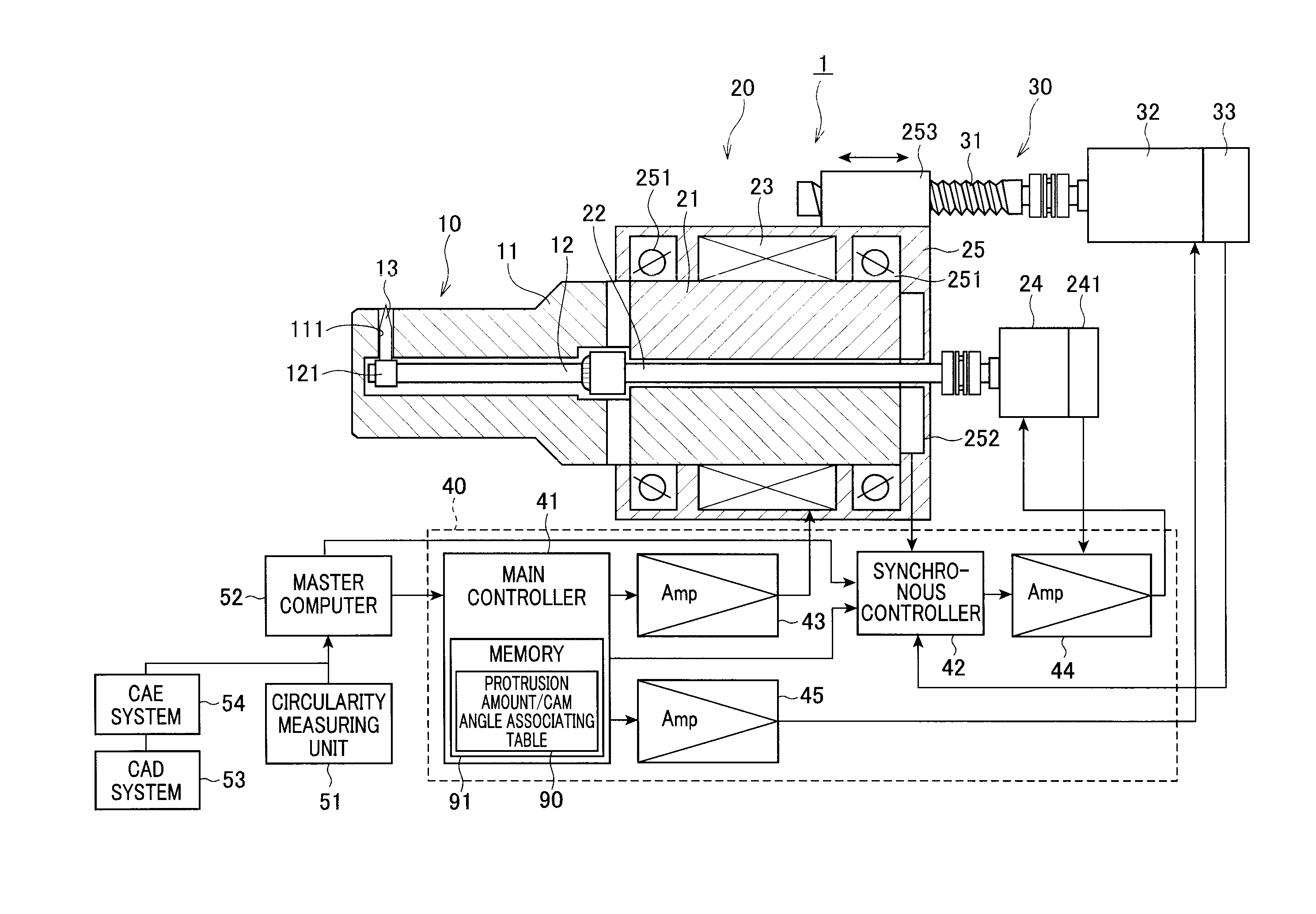
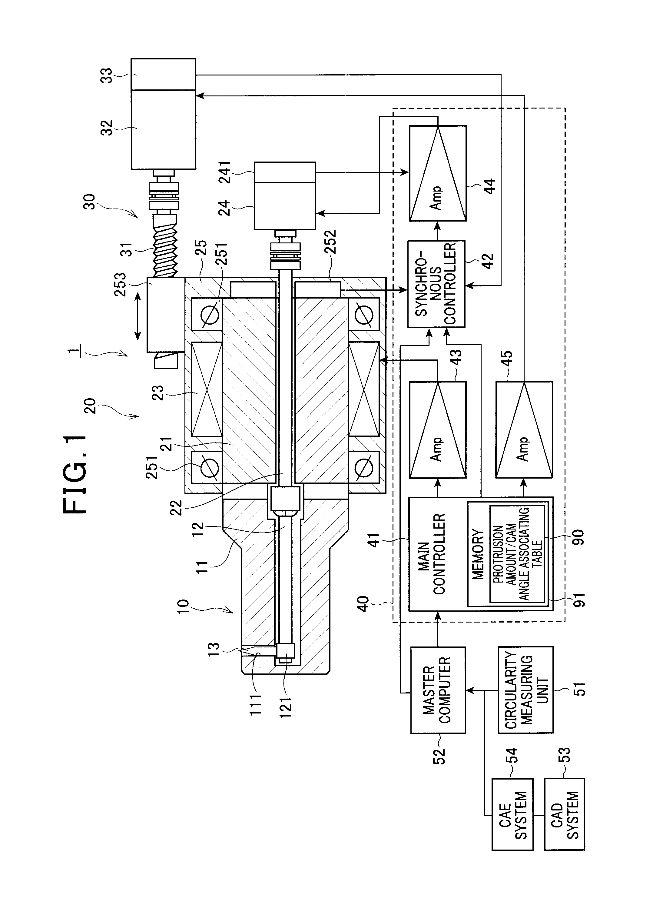
[0039]FIG. 1 is a diagram showing the construction of a non-circular bore processing device 1 according to an embodiment of the preset invention.

[0040]The non-circular bore processing device 1 inserts a processing head 10 into a bore of a cylinder block of a vehicle engine as a work and performs boring processing. The non-circular bore processing device 1 comprises a rotational driving mechanism 20 for rotating the processing head 10, a reciprocating mechanism 30 for advancing and retracting the rotational driving mechanism 20, a controller (cam driving device) 40 for controlling the above parts, a circularity measuring unit 51 for measuring the internal shape of the bore of the work, and a master (superordinate) computer 52 analyzing the measurement result of the circularity measuring unit 51 and outputting an analysis result to the controller 40.

[0041]The rotational...


PUM

PropertyMeasurementUnit
Angleaaaaaaaaaa
Speedaaaaaaaaaa
Shapeaaaaaaaaaa

Abstract

A cam driving device for a processing device including a cylindrical member, a rotational shaft that has a mount hole formed on the outer peripheral surface thereof, a cam, and a tool that is mounted in the mount hole of the cylindrical member so that the tool can be protruded and retracted through the mount hole in a radial direction of the rotational shaft in accordance with a profile of the cam. The cylindrical member and the rotational shaft are axially reciprocated to process a non-circular bore, including a storage unit for storing a data table representing associating relationship between a rotational angle of the cam and a protrusion amount of the tool which is provided on the basis of the rotational angle of the cam, and a controller for advancing or retarding the rotational angle of the rotational shaft according to the data table stored in the storage unit.

Description

INCORPORATION BY REFERENCE[0001]The present application claims priority under 35 U.S.C. §119 to Japanese Patent Application No. 2009-118756 filed on May 15, 2009. The content of the application is incorporated herein by reference in its entirety.BACKGROUND OF THE INVENTION[0002]1. Field of the Invention[0003]The present invention relates to a cam driving device and a processing method, and particularly to a cam driving device and a processing method that are suitably used for a processing apparatus for processing the inner peripheral surface of a non-circular bore.[0004]2. Description of the Related Art[0005]It has been general in a manufacturing process of vehicles that a bore of a cylinder block of an engine is formed by a cutting work and then a cylinder head, a crank case, etc. are installed in the cylinder block. Furthermore, a piston is also mounted in the bore. When an actual engine is driven, fuel in the engine is combusted, and the piston is heated by combustion gas and exp...

Claims


Application Information

Patent Timeline
IPC IPC(8): B23Q5/00
CPCB23B29/03482B23B41/04G05B2219/42189B23Q17/20G05B2219/34343B23B41/12
Inventor KUME, MASAOTAKAHASHI, KEISUKE
Owner HONDA MOTOR CO LTD
Why Eureka
Try Eureka