Filter with quick attachment features

Active Publication Date: 2010-12-02
PARKER INTANGIBLES LLC
View PDF2 Cites 14 Cited by
  • Summary
  • Abstract
  • Description
  • Claims
  • Application Information

AI Technical Summary

Benefits of technology

[0008]The attachment structure further includes a pair of retaining clips also located on opposite side of the canister, but toward the upper end thereof. Each clip is in substantial axial alignment along the side of the housing with a respective pivot, and has a radially flexible axial body portion, and an integral tab portion at the free end of the retaining clip. An outwardly-projecting stand-off is also provided adjacent the tab end of the retaining clip, with the stand-offs of the clips being dimensioned to be closely received within the arms of the bracket, and preventing the tab ends of the clips from being pressed against the sides of the canister; or in other words, allowing some free space between the tab ends of the clips and the canister such that the tabs can be pressed inwardly when it is desired to remove the filter from the bracket, as will be more fully described herein.
[0009]The bracket for the filter includes a body and a pair of side walls, with the sidewalls projecting outwardly from the body in spaced-apart relation such that the filter can be closely received therebetween. Each of the sidewalls includes i) a hook-shaped slot dimensioned to receive a respective

Problems solved by technology

This technique also requires sufficient axial space, requires access to the spring clip on the back of the filter, and has the same issues as described above with respect to the hoses.
While the above described attachment techniques and connections have received some acceptance in the market, it is believed there is a demand in the industry for a connection which does no

Method used


Image

  • Filter with quick attachment features
  • Filter with quick attachment features
  • Filter with quick attachment features

Examples


Embodiment Construction

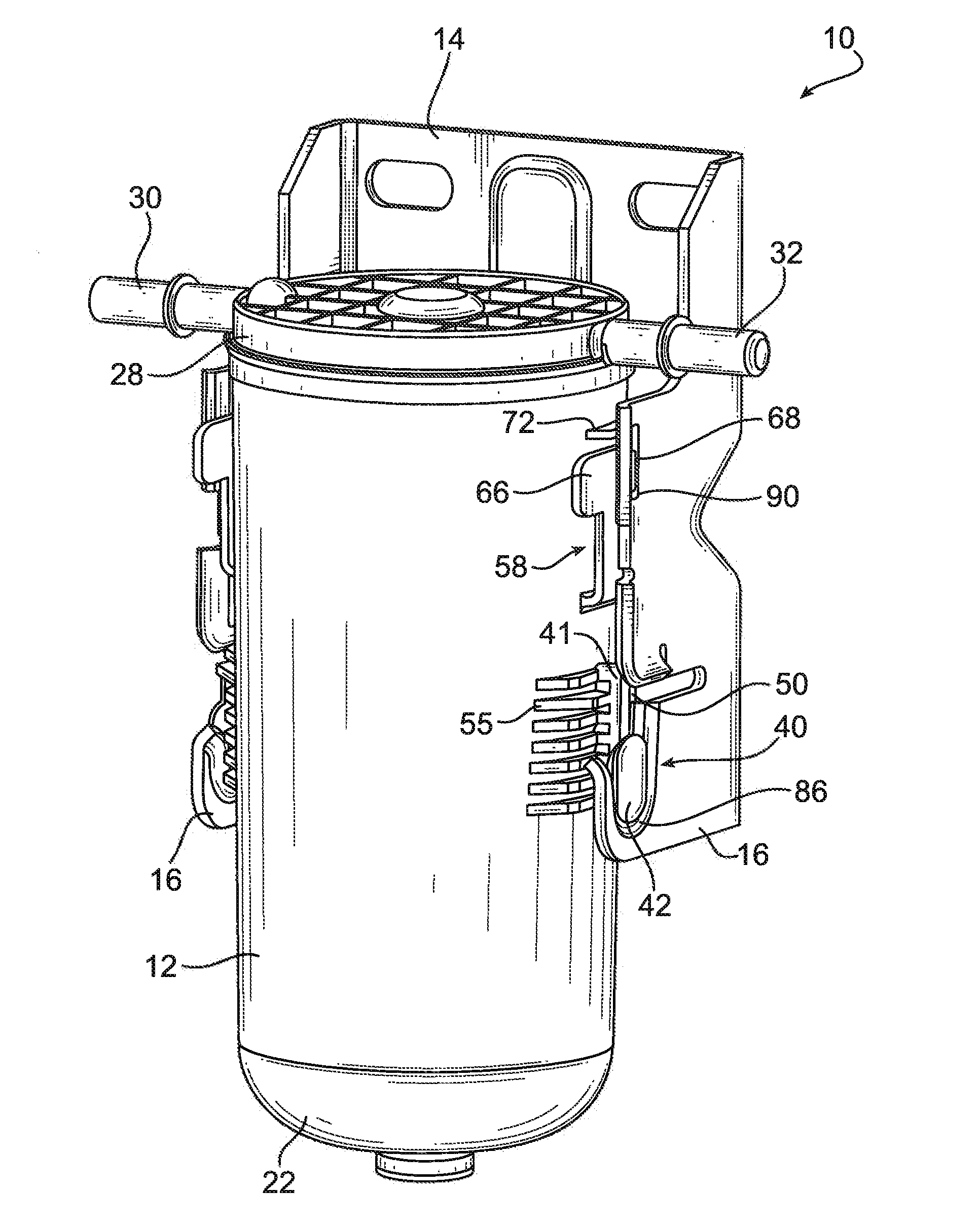
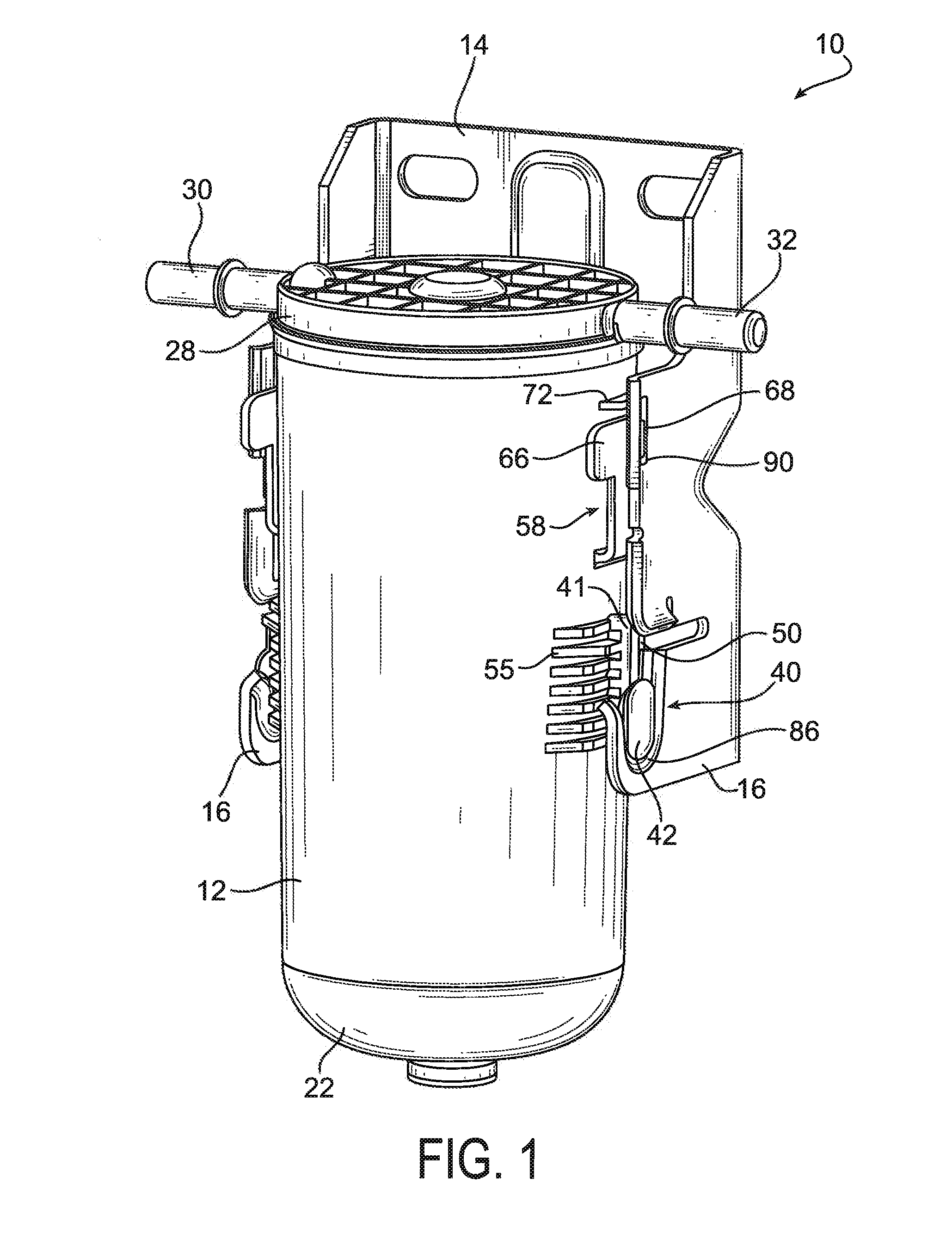
[0017]Referring to the drawings, and initially to FIG. 1, a filter assembly according to the present invention is indicated generally at 10. Filter assembly 10 includes a filter 12 and a support bracket 14 with sidewalls 16. Filter 12 and bracket 14 have a quick attachment feature as will be described below.

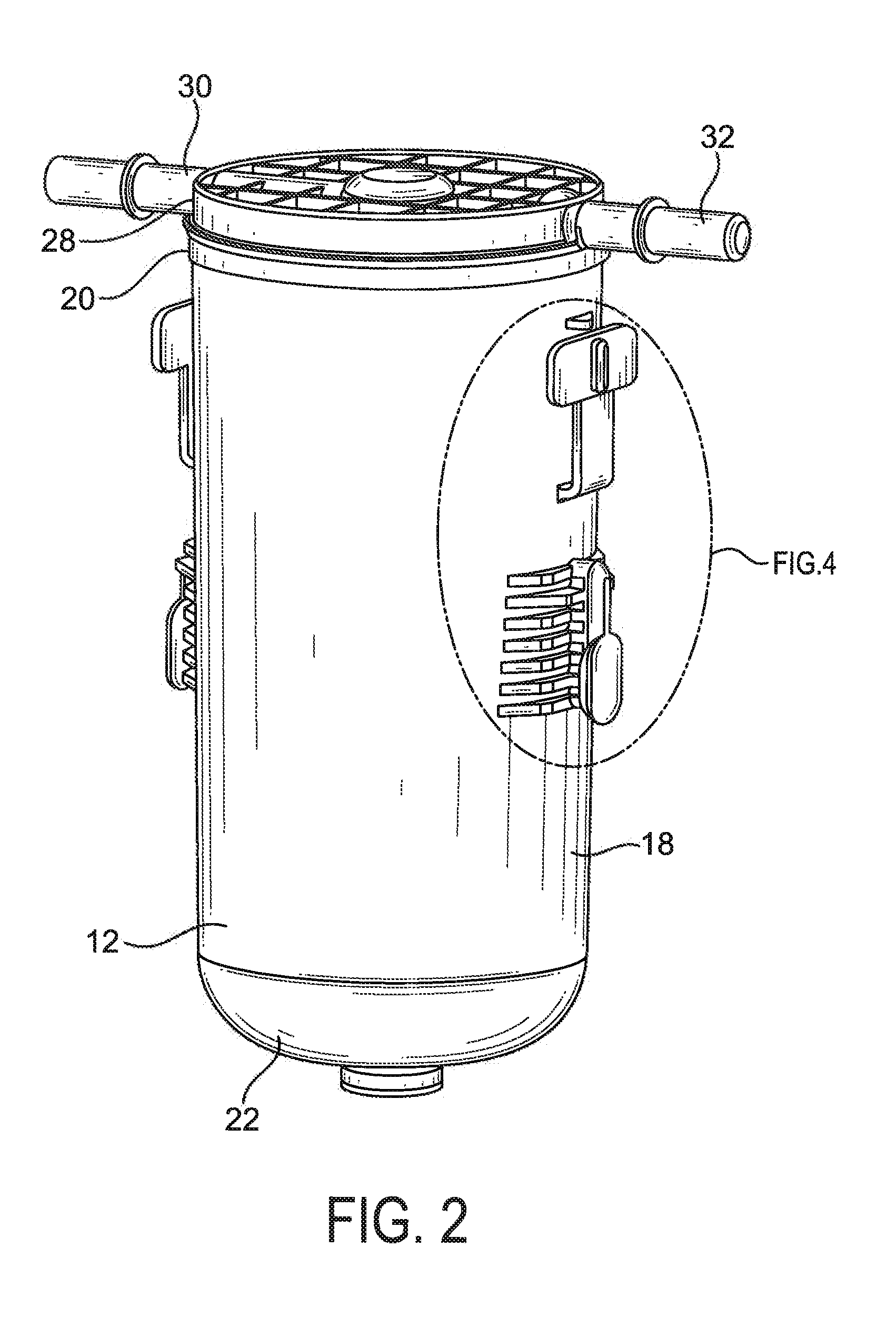
[0018]Referring now to FIGS. 2-4, filter 12 includes an outer cup-shaped canister or housing 18 with an open upper end 20 and a closed lower end 22. A drain 23 (FIG. 3) can be located in a threaded opening 24 in the lower end of the housing to allow periodic removal of water from the filter. Canister has a generally cylindrical shape, although it can be other shapes; and can be formed from material appropriate for the particular application, such as plastic or metal.

[0019]An end cap or lid 28 is attached such as by adhesive, welding or other bonding means to the upper end of the canister. End cap 28 includes an inlet port or tube 30 with an internal opening 31 to direct fluid to ...


PUM

PropertyMeasurementUnit
Lengthaaaaaaaaaa
Flexibilityaaaaaaaaaa

Abstract

A quick attachment feature for a filter includes i) a pair of radially-outward projecting pivots on opposite sides of the filter canister toward a lower end thereof; and ii) a pair of flexible retaining clips also located on opposite side of the canister toward the upper end thereof, each clip in substantial axial alignment along the canister with a respective pivot. The filter can be supported in a bracket including a pair of side walls, each of the side walls including i) a hook-shaped opening dimensioned to receive a respective pivot on the filter, and allow the filter to pivot from an orientation at an angle to the longitudinal axis of the bracket, to an orientation where the filter is substantially axially-aligned with the bracket; and ii) a catch dimensioned to engage and retain a respective retaining clip, when the filter is substantially aligned with the bracket.

Description

FIELD OF THE INVENTION[0001]The present invention relates generally to fluid filters, and an attachment and technique for mounting such filters to a bracket or other support device.BACKGROUND OF THE INVENTION[0002]Certain fluid filters are supported on a bracket (or other support device), and have a quick-release feature to allow the filter to be quickly and easily removed from such bracket. In a vehicle for example, it can be desirable to have a bracket on an engine, in the engine compartment, or other appropriate support location on the vehicle, and to have quick attachment means for mounting the filter to the bracket, and for removing the filter when it is desirable, for example, to access the filter remotely for repair, or for replacement of a spent element.[0003]The type of attachment (or connection) for such application should be robust and secure, and prevent inadvertent detachment of the filter from the bracket during use. Nevertheless, it should be relatively easy to attach...

Claims


Application Information

Patent Timeline
IPC IPC(8): B01D35/30B01D29/00
CPCB01D2201/4023B01D35/30B01D29/96B01D35/02
Inventor CLAUSEN, MICHAEL D.
Owner PARKER INTANGIBLES LLC
Why Eureka
Try Eureka