Device for measuring the intensity of an electric current and electric appliance including such device

a technology of electric current and measuring device, which is applied in the direction of measurement device, voltage/current isolation, instruments, etc., can solve the problems of falsifying the measurement of intensity, requiring specialized installation of current transformers, and having a limited measurement dynamic, etc., to achieve high measurement dynamic, simple structure, and economic design.

Active Publication Date: 2010-12-02
SOCOMEC
View PDF19 Cites 17 Cited by
  • Summary
  • Abstract
  • Description
  • Claims
  • Application Information

AI Technical Summary

Benefits of technology

[0007]The present invention proposes a solution to this problem with a device for measuring current intensity having a simple, economic design, compact size for easy integration with any type of electric apparatus, offering high measurement dynamic, versatility, and th...

Problems solved by technology

However, these current transformers require specialized installation.
They are fairly cumbersome and have limited measurement dynamic.
However, these induction sensors are particularly susceptible to nearby or parasitic magnetic fields which will falsify the measurement of intensity.
It is possible to overcome this problem by increasing the section of the magnetic circuit, but this enlarges its size.
Furthermore, this type of sensor has a very limited measurement dynamic when used in an open loop configuration.
Nevertheless, using high quality Rogowski coils in industry is very complex, costly, and hard to replicate because these coils require the linear density of the windings to be constant, as well as the section of the windings.
Additionally, constructing an open measurement device, that is, one made in two sections to faci...

Method used


Image

  • Device for measuring the intensity of an electric current and electric appliance including such device
  • Device for measuring the intensity of an electric current and electric appliance including such device
  • Device for measuring the intensity of an electric current and electric appliance including such device

Examples


Embodiment Construction

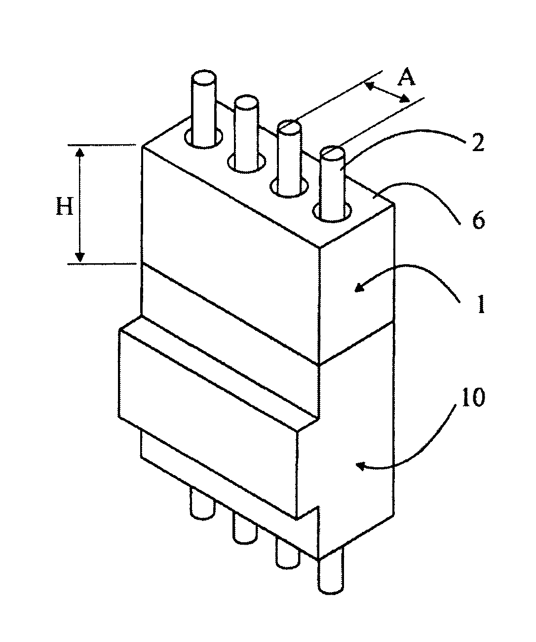
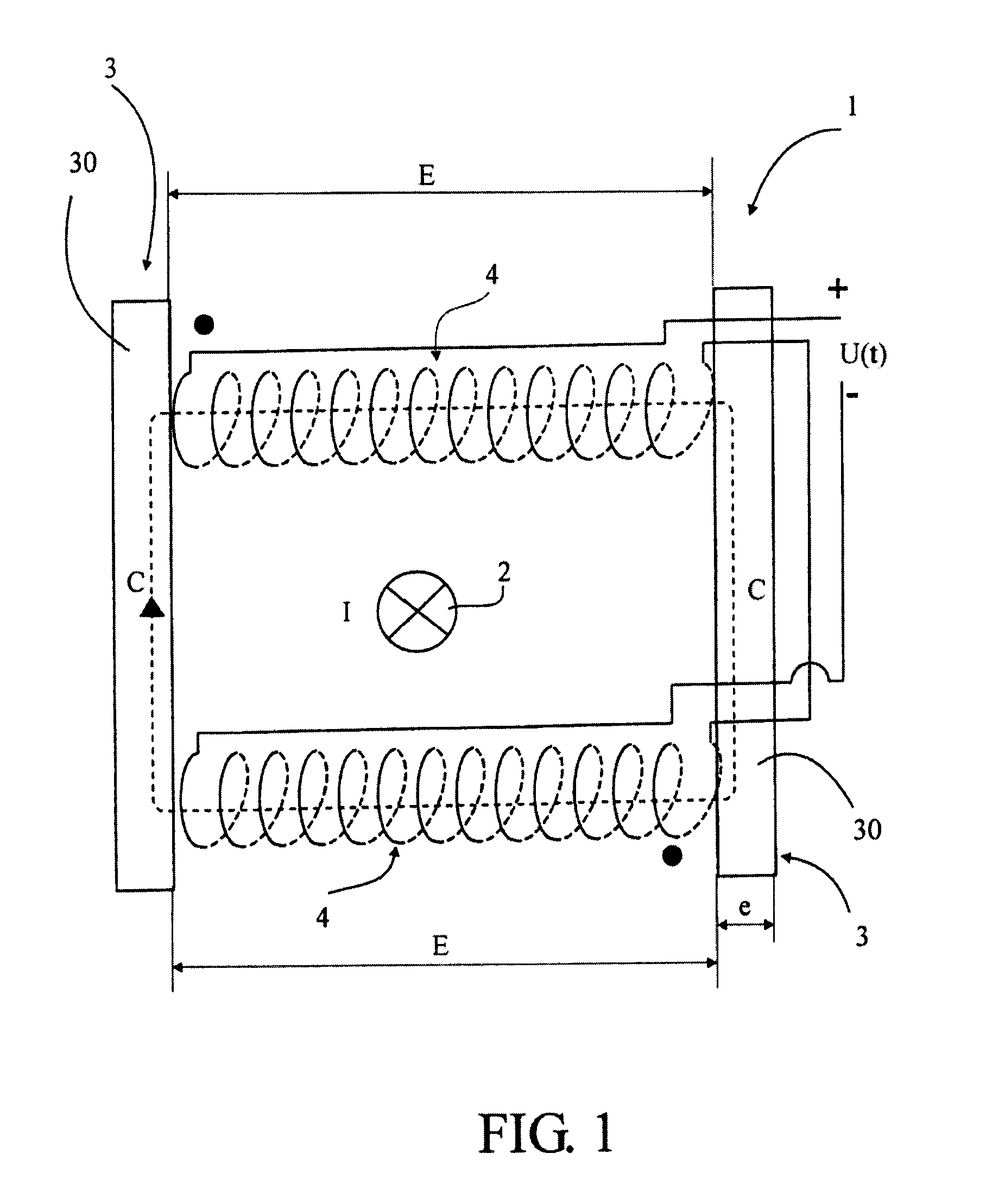
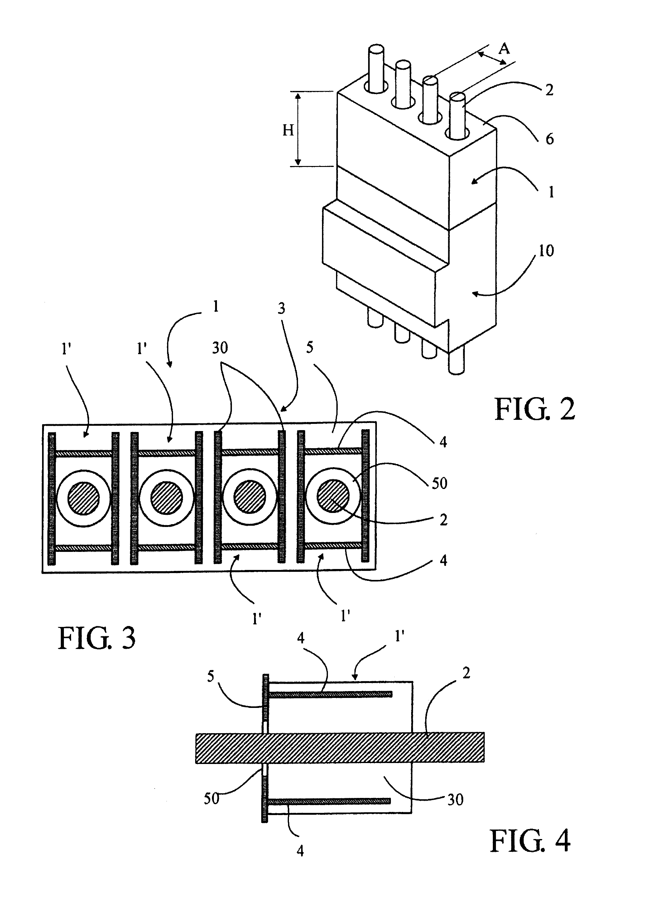
[0025]The principle of measurement device 1 according to the invention for measuring the intensity I of current passing through an electrical conductor 2 or a current line, hereafter called conductor 2, is illustrated in FIG. 1. It utilizes the magnetic field induced around conductor 2 by the current I to be measured. In the present invention, the circulation of the lines of this magnetic field is controlled on a closed path C, formed of at least one open magnetic circuit 3 and defining at least two gaps E closed by at least two electric coils 4, hereafter called coils 4, which are wound perpendicular to the direction in which the field circulates and which occupy more than one-third of closed path C. The Ampere theorem is applied to path C by decomposing the field circulating in the air through coils 4 and the field circulating in the magnetic circuit 3. If a magnetic circuit 3 with high magnetic permeability is chosen, the component of the magnetic field circulating in the magneti...


PUM


Abstract

A device for measuring the intensity of an electric current which has a simple and economical design and offers a high measurement dynamic compatible with combined measurement, protection and energy metering applications. The device (1) is insensitive to parasitic fields and to the position of the electric conductor to be measured, and that can be opened to facilitate placement thereof. The device (1) defines a closed path (C), about a conductor (2) for the circulation of the lines of magnetic field induced by the current to be measured, and the path is formed by two plates (30) having a high magnetic permeability separated by two air gaps (E) closed by two identical and opposed electric coils (4) for supplying a voltage proportional to the derivative of the intensity (I) of the current to be measured. The device (1) reduces the is compact so that it can be easily integrated into any type of electric appliance.

Description

TECHNICAL DOMAIN[0001]The present invention concerns a device for measuring the intensity of an electric current comprising at least one magnetic circuit disposed near an electric conductor traversed by a current to be measured in order to channel the magnetic field induced around the conductor by the current to be measured, at least one electric coil associated with the magnetic circuit to deliver voltage proportional to the derivative of the intensity of the current to be measured, and at least one voltage processing module to deliver the value of the measured intensity. The invention also concerns an electric apparatus equipped with such a device, the electrical apparatus possibly consisting of a shutoff device such as a switch, a commutator switch, a circuit breaker, or any other equivalent monophase or polyphase device, with or without a neutral.PRIOR ART[0002]Several types of devices exist for measuring the intensity of an alternating current passing through an electric conduc...

Claims


Application Information

Patent Timeline
IPC IPC(8): G01R15/18
CPCG01R15/186G01R15/183G01R15/181
Inventor KERN, CHRISTIAN
Owner SOCOMEC
Why Eureka
Try Eureka