
Device For Detecting A Thread

a technology for detecting devices and threads, applied in the direction of counting objects on conveyors, instruments, transportation and packaging, etc., can solve the problems of reducing the reliability of measuring, affecting the accuracy of measurement, so as to reduce the disturbance or avoid the disturbance of air flow, reduce the disturbance of measuring, and improve the effect of economic design

Inactive Publication Date: 2008-09-11
OERLIKON TEXTILE GMBH & CO KG
View PDF3 Cites 7 Cited by
  • Summary
  • Abstract
  • Description
  • Claims
  • Application Information

AI Technical Summary

Benefits of technology

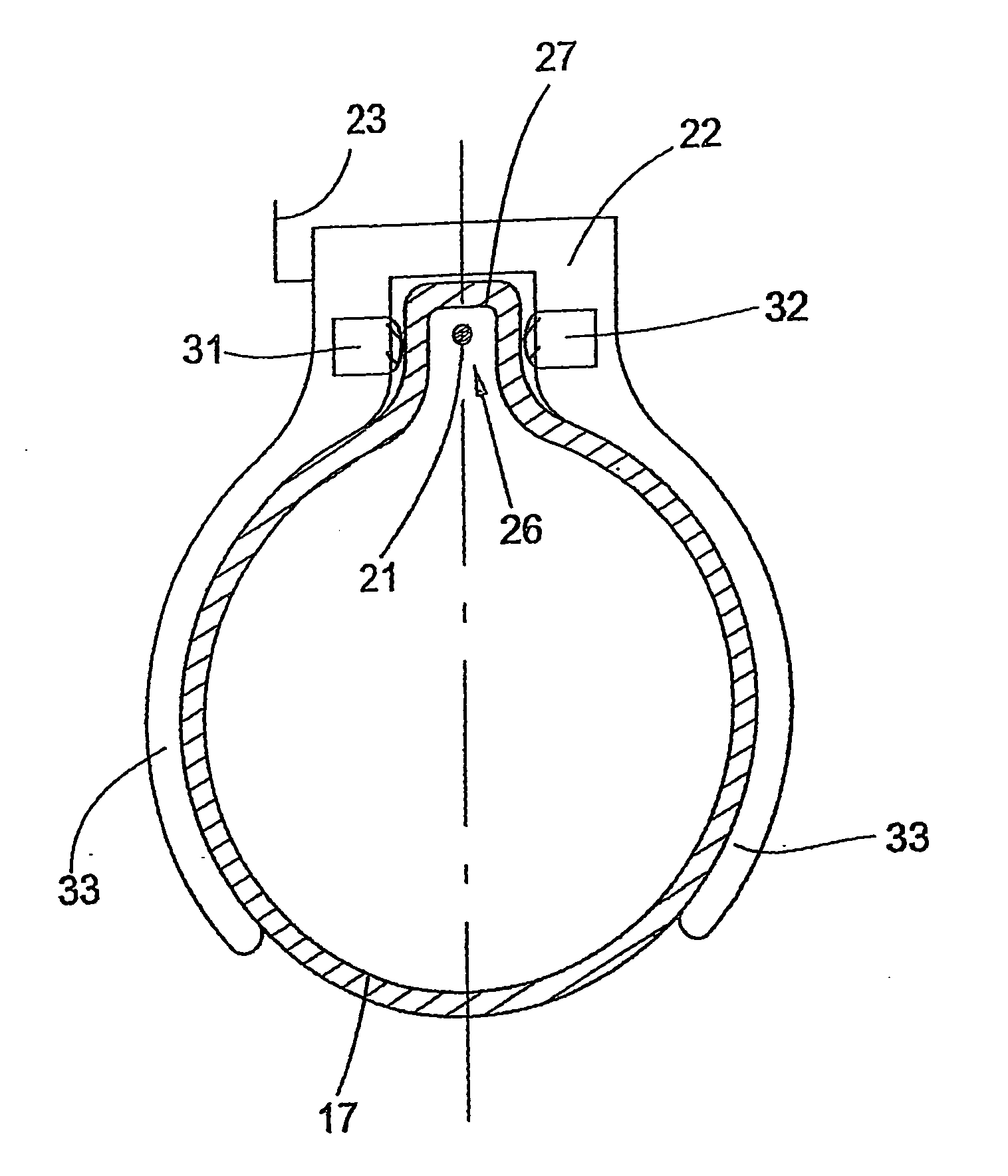
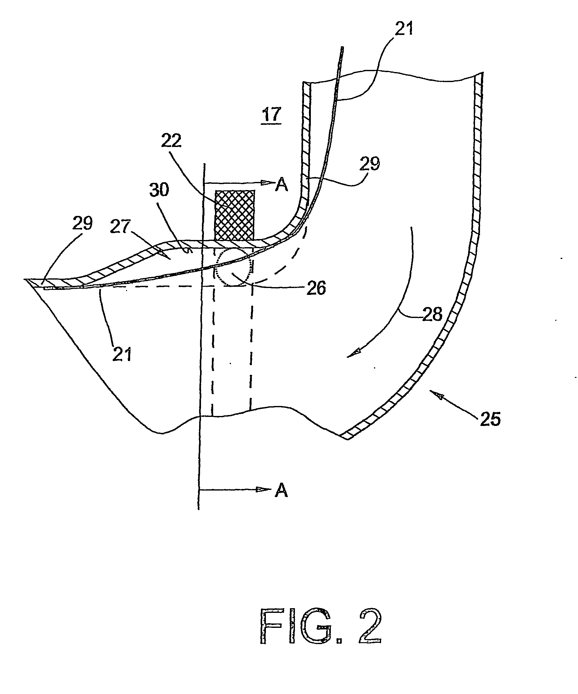
[0012]In the device according to the invention, the thread is guided in such a way that it moves in the measuring field at a spacing from the wall of the suction pipe and can be positioned well in the measuring field. Owing to its “fluttering movement” transverse to its running direction, the thread can be detected particularly easily and reliably. The transmitter and receiver are arranged in such a way that the recess runs between them. It is therefore possible to produce a spacing between the transmitter and receiver which is significantly smaller than the diameter of the suction pipe. The transmitter and receiver can therefore be used in a simple, more economic design with a reliable detection of the thread remaining ensured.
[0013]If at least the beginning of the recess is located in the region of the curvature of the suction pipe, if the wall of the suction pipe forms the guide of the detected thread at the beginning and end of the recess and if the thread course of the detected thread determined by the guide is always located inside the suction pipe, the thread being tensed inside the recess and the thread course crossing the measuring field inside the recess and at least being partly spaced apart from the bottom of the recess, a spacing between the thread and the bottom of the suction pipe inside the measuring field placed in the region of the recess can easily be achieved. Even if it is possible in the scope of the invention that the measuring field runs between the transmitter and receiver through holes which are flush with one another, which penetrate the wall of the suction pipe, it is advantageous to configure the suction pipe in the region of the sensor mechanism in such a way that no disturbances take place owing to openings in the wall of the suction pipe at which deposits could also form. The suction pipe is transparent for this purpose. An economical design of a transparent suction pipe is made possible by the use of polypropylene as the transparent material.
[0014]Owing to a configuration of the suction pipe with the recess beginning so gradually in the flow direction that the air flow is not, or only insubstantially, disturbed, disturbances of the air flow can also be minimized or avoided.

Problems solved by technology

The optical systems facing one another in the form of lenses become soiled as a function of the loading of the thread with impurities after a certain period of use, whereby the reliability of the measuring reduces.
Both the large spacing and the soiling bring about a weakening of the signals of the sensor mechanism.
The measuring device becomes soiled and is subjected to functional disturbances or functional failures.
Performance losses to the suction occur as a result.
The air flow is disturbed and weakened.
Dirt entrained by the thread, in particular softener, no longer reaches the sensors, but the openings through the wall of the suction channel and the edges connected thereto, can lead to disruptions of the air flow in the suction channel and entail the formation of accumulations of dirt, for example the formation of piles of lint.
Secondary air is drawn into the suction channel through the openings, and this leads to a loss of performance of the suction device.
This makes a more costly sensor mechanism necessary if reductions are not to be accepted in the thread detection.

Method used


Image

  • Device For Detecting A Thread
  • Device For Detecting A Thread
  • Device For Detecting A Thread

Examples


Embodiment Construction

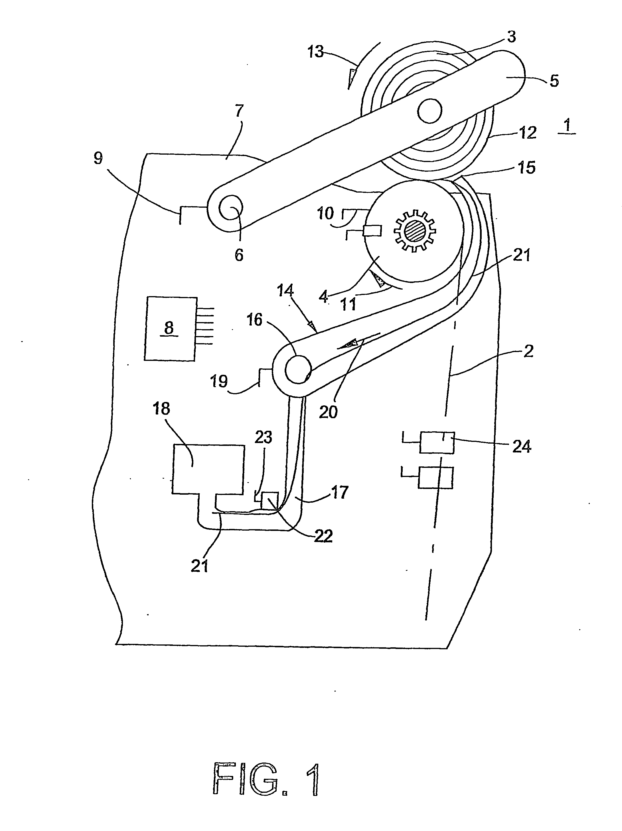
[0020]FIG. 1 shows a winding head of a textile machine producing cross-wound bobbins. FIG. 1 shows a situation at the winding head 1, in which the thread run has been interrupted after a thread cut owing to a yarn defect and measures to remove the yarn defect, a so-called clearing, have been introduced. The thread run during operation of the winding head 1 is identified by the dashed line 2. During operation of the winding head 1, the thread is drawn off from a thread source, not shown. The thread source can be a supply bobbin or a spinning device.

[0021]The thread is wound onto a cross-wound bobbin 3 acting as a take-up bobbin. For clearing, the defective thread piece, which has been taken onto the cross-wound bobbin 3, has to be so completely unwound therefrom, that when the thread is cut, the yarn defect is located in the cut-off thread part. The cross-wound bobbin 3, in the view of FIG. 1, has already been lowered again onto the winding roller 4. The cross-wound bobbin 3 is held ...


PUM


Abstract

The device is intended for the detection of a thread during the detection of the ends of threads (21) in suction pipe (17) crossflown by air, comprising a sensor device (22) having a transmitter (31) and a receiver (32) in a textile machine that produces cross-wound bobbins. A measuring field (26) is formed between the transmitter (31) and the receiver (32). The suction pipe has a curvature in the area of the measuring field (26). The measuring field (26) is arranged in the proximity of the smaller radius of the suction pipe (17), which has a recess (27) oriented in the running direction of the suction pipe (17) in order to form the measuring field (26). The suction pipe (17) is curved upstream and downstream of the measuring field (26) in such a way that the detected thread is tensed inside the recess (27) in such a manner that it is spaced at least partly from the bottom of the recess (27) in the measuring field (26), thereby making it possible to easily and reliably detect the thread.

Description

CROSS-REFERENCE TO RELATED APPLICATIONS[0001]This application claims the benefit of German patent application 10 2004 003 174.6, filed Jan. 22, 2004, herein incorporated by reference.BACKGROUND OF THE INVENTION[0002]The invention relates to a device for detecting a thread during the detection of thread ends in a suction pipe through which air flows, with a sensor mechanism comprising a transmitter and a receiver for detecting a thread with the features of the preamble of claim 1.[0003]Suction pipes of this type are equipped, for example, with devices for detecting a thread, in order to ascertain the detection of the thread end on the take-up bobbin side or the supply bobbin side, which thread end is to be supplied to a thread connecting mechanism on a winding head. Suction pipes are also equipped with a device of the type, which are used on cop preparation mechanisms, in order to ascertain whether it was possible to detect the thread, which is then to be provided at a suitable locat...

Claims


Application Information

Patent Timeline
Patent Type & Authority Applications(United States)
IPC IPC(8): B65H67/08B65H63/036
CPCB65H63/036B65H2701/31B65H67/085
Inventor PETERS, ERWINWEGMANN, THOMAS
Owner OERLIKON TEXTILE GMBH & CO KG
Learn More