Thrust bearing and suspension for vehicle

a thrust bearing and vehicle technology, applied in the direction of bearing components, resilient suspensions, shafts and bearings, etc., can solve the problems of not being able to provide a good sealing and having detrimental effects on the life of suspension thrust bearings, so as to reduce water or other pollutant particles. the effect of infiltration

Active Publication Date: 2016-05-17
AB SKF
View PDF27 Cites 1 Cited by
  • Summary
  • Abstract
  • Description
  • Claims
  • Application Information

AI Technical Summary

Benefits of technology

[0010]More particularly, the present invention aims to provide a robust suspension thrust bearing device capable of withstanding the forces exerted by the suspension spring and of absorbing some of the vibrations emitted by the spring, while reducing any infiltration of water or other pollutant particles.
[0011]The present invention also aims to provide a suspension thrust bearing device which is particularly reliable over time and is of simple and economic design.
[0020]The support cap may comprise an external sealing lip in frictional contact with the bearing cap. The bearing cap may also comprise a hook extending radially inwards and cooperating with the external sealing lip for axially retaining the bearing cap relative to the support cap. There is thus available a unitary assembly which can be stored, transported, handled and mounted with a relatively low risk of axial detachment of the elements constituting it by virtue of the cooperation between the sealing lip of the support cap and the hook of the bearing cap.

Problems solved by technology

The suspension thrust bearing of this document does not make it possible to provide a good sealing of the rolling bearing.
Therefore, under certain conditions, for example when the vehicle is driving along a flooded road or alternatively when the vehicle is being cleaned with a high-pressure jet of water, there may be some infiltration of water or other pollutant particles into the rolling bearing with detrimental effects on the life of the suspension thrust bearing.

Method used


Image

  • Thrust bearing and suspension for vehicle
  • Thrust bearing and suspension for vehicle
  • Thrust bearing and suspension for vehicle

Examples


Embodiment Construction

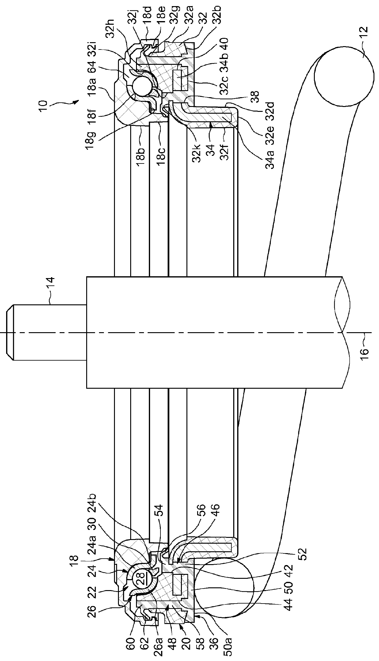
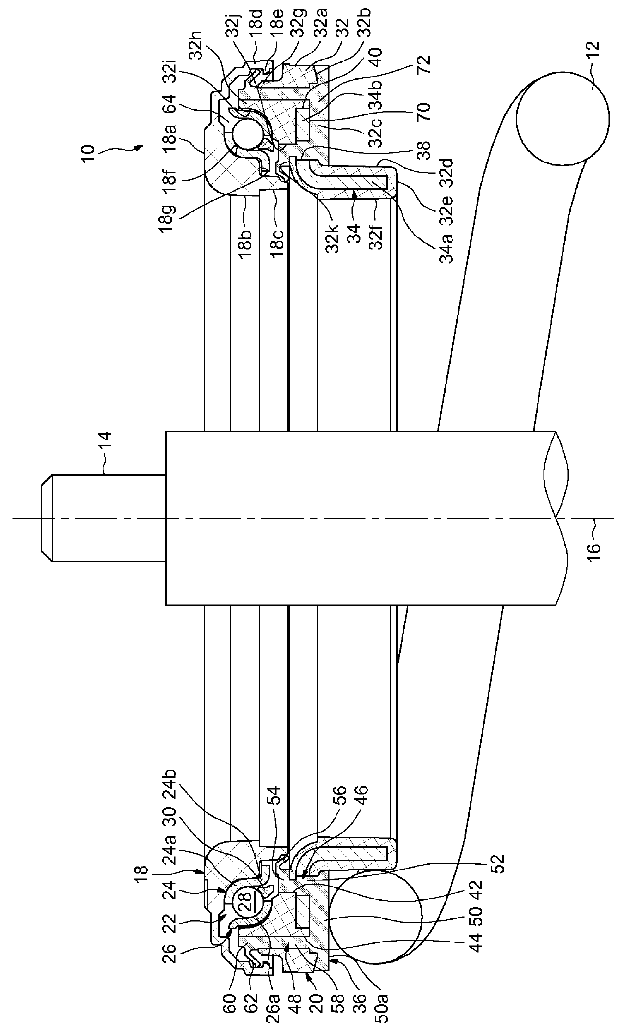
[0028]FIG. 1 depicts a suspension thrust bearing device, denoted by the general reference number 10, designed to be mounted between an element of the chassis of a motor vehicle and a helical-type suspension spring 12. The device 10 is arranged around a shock absorber rod 14, of axis 16 assumed to be vertical, the rod being elongated axially in the form of a cylinder of revolution. The suspension spring 12 is mounted around the shock absorber rod 14.

[0029]The device 10, of axis 16, comprises an upper bearing cap 18 designed to come into contact against a filtering elastic block interposed between the device and the chassis of the vehicle, a lower support cap 20 forming a bearing means for the spring 12, and a rolling bearing 22 arranged axially between the caps and forming an axial thrust bearing.

[0030]The bearing cap 18 may consist of an integral part produced from plastic, for example polyamide PA 6.6 optionally reinforced with glass fibres. The bearing cap 18 comprises an upper ra...


PUM


Abstract

The suspension thrust bearing device for a motor vehicle comprises a rolling bearing forming an axial thrust bearing and provided with an upper ring, with a lower ring and with at least one row of rolling elements arranged between the rings, a bearing cap in contact with the upper ring, and a support cap in contact with the lower ring and forming a bearing means for a suspension spring. The support cap comprises a body of rigid material and seals of flexible material fixed to the body and comprising dynamic sealing lips in contact with the bearing cap or one of the rings of the rolling bearing and delimiting radially a sealed space containing at least the rolling elements of the rolling bearing. The support cap further comprises an annular ring to which the lower ends of the seals are connected and forming a bearing surface for the suspension spring.

Description

CROSS-REFERENCE[0001]This application is the US national stage of International Application No. PCT / EP2010 / 060398 filed on Jul. 19, 2010, which claims priority to French Application No. FR 0955311 filed Jul. 29, 2009.FIELD OF INVENTION[0002]The present invention relates to the field of suspension thrust bearing devices used in particular in motor vehicles in the suspension struts of the steered wheels.BACKGROUND OF THE INVENTION[0003]The invention relates more particularly to a suspension thrust bearing device comprising an upper ring and a lower ring between which is arranged at least one row of rolling elements, for example, balls or rollers. The upper and lower rings are generally mounted in contact with lower and upper bearing or support parts, such as cups or caps. The upper and lower caps form a housing for the rings of the rolling bearing and provide the interface between the rings and the surrounding elements.[0004]The suspension thrust bearing device is arranged in the uppe...

Claims


Application Information

Patent Timeline
Patent Type & Authority Patents(United States)
IPC IPC(8): F16C33/76F16C19/10F16C19/16B60G15/06F16C33/60
CPCB60G15/067F16C19/10F16C33/60F16C33/761B60G2204/418F16C2326/05
Inventor CORBETT, RICHARDDUBUS, JEROMEMONTBOEUF, BRUNOVIAULT, SAMUEL
Owner AB SKF
Why Eureka
Try Eureka