Filtration irrigation device
a technology of filtration irrigation and filter membrane, which is applied in the direction of lighting and heating equipment, combustion types, applications, etc., can solve the problems of difficult to block the outflow passage of impurities, and achieve the effect of improving or avoiding the blockage reducing the water penetration rate of reducing the impact speed of the impurities carried in the water on the porous filter membran
- Summary
- Abstract
- Description
- Claims
- Application Information
AI Technical Summary
Benefits of technology
Problems solved by technology
Method used
Image
Examples
embodiment 1
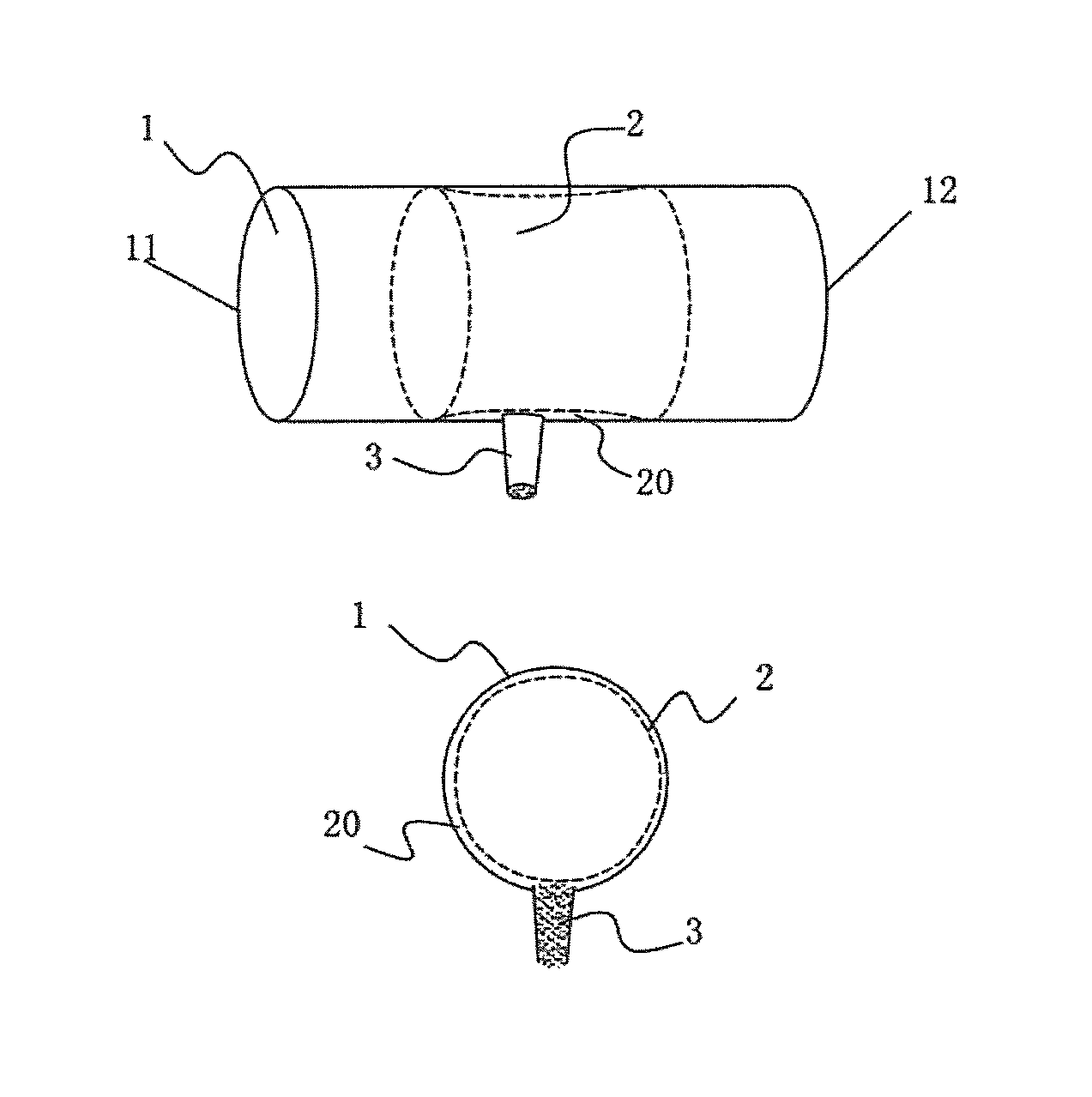
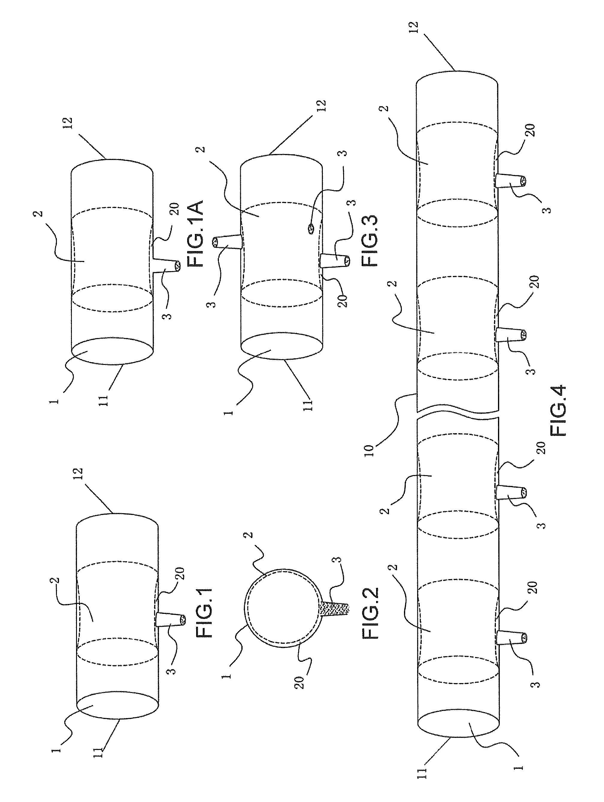
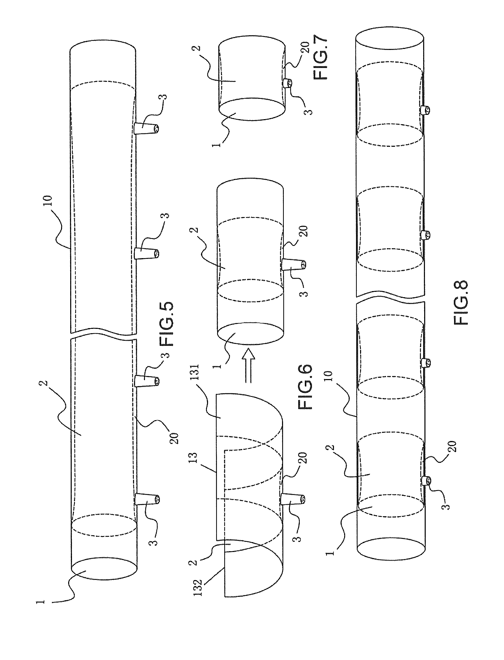
[0086]FIGS. 1 to 8 illustrate the structural diagrams of the infiltration irrigation apparatus according to Embodiment 1 of the present invention. As illustrated in FIG. 1, the infiltration irrigation apparatus according to the embodiment includes a water passing chamber 1, a porous filter membrane 2 and a flow restrictor 3. The water passing chamber 1 has a water inlet 11 and a water outlet 12. The porous filter membrane 2 covers a complete circumference of inner wall of the water passing chamber 1. The edges of both ends of the porous filter membrane 2 may closely engage with the inner wall of the water passing chamber 1 and then become waterproof, so as to form a filtration section 20 between the porous filter membrane 2 and the inner wall of the water passing chamber 1 covered thereby. The flow restrictor 3 is disposed on a sidewall of the water passing chamber 1 corresponding to the porous filter membrane 2. Each flow restrictor 3 has one or more restricting orifices, an inlet ...
embodiment 2
[0109]FIGS. 9 to 13 illustrate structural diagrams of Embodiment 2 of the present invention. The basic structure of this embodiment is substantially the same as that of Embodiment 1, the descriptions of the same portions are omitted herein, and the difference is the manner of disposing the porous filter membrane 2. In this embodiment, provided that the total water seepage capability of the porous filter membrane 2 is larger than that of the flow restrictor 3, the porous filter membrane 2 may be just disposed on a part of the circumference of the inner wall of the water pipe 1, i.e., it only covers a part of the inner circumferential wall of the water passing chamber 1 corresponding to the flow restrictor 3. In addition, the edges of the porous filter membrane 3 closely engage with the inner of the water pipe to proof water, so as to form an isolated filtration section 20 between the porous filter membrane 2 and the inner wall of the water pipe covered thereby. The water cannot becom...
embodiment 3
[0116]FIGS. 14 to 19 illustrate structural diagrams of Embodiment 3 of the present invention. The basic structure and the principle of this embodiment are substantially the same as that of Embodiment 1, and the descriptions of the same portions are omitted herein. As illustrated in FIGS. 14 to 19, this embodiment differs from Embodiment 1 in that the porous filter membrane 2 is bag-shaped, and the filtration section 20 is formed in a bag of the porous filter membrane 2. During the infiltration irrigation, the water cannot become irrigation water until it enters the bag through the bag-shaped porous filter membrane 2 (i.e., into the filtration section 20), and flows out of the tubular infiltration irrigation apparatus through the flow restrictor 3.
[0117]In addition to the effect of Embodiment 1, since a bag-shaped porous filter membrane 2 is used, a blockage is more difficult to be caused. Because firstly, as compared with the flush porous filter membrane, the bag-shaped porous filte...
PUM
 Abstract
Description
Claims
Application Information
 - R&D
- Intellectual Property
- Life Sciences
- Materials
- Tech Scout
- Unparalleled Data Quality
- Higher Quality Content
- 60% Fewer Hallucinations
Browse by: Latest US Patents, China's latest patents, Technical Efficacy Thesaurus, Application Domain, Technology Topic, Popular Technical Reports.
© 2025 PatSnap. All rights reserved.Legal|Privacy policy|Modern Slavery Act Transparency Statement|Sitemap|About US| Contact US: help@patsnap.com


