Filtration irrigation method, filtration irrigation device and the manufacturing method thereof

a technology of filtration irrigation and filtration device, which is applied in the direction of watering device, horticulture, agriculture, etc., can solve the problems of difficult blockage of the outflow passage of impurities, and achieve the effect of reducing the water penetration rate improving or avoiding the blockage of the porous filter membran

Inactive Publication Date: 2012-07-19
ZHU JUN
View PDF4 Cites 7 Cited by
  • Summary
  • Abstract
  • Description
  • Claims
  • Application Information

AI Technical Summary

Benefits of technology

[0005]An object of the present invention is to provide an infiltration irrigation method, an infiltration irrigation apparatus and a method for manufacturing the same, which are capable of automatically clearing the obstructions by sufficiently utilizing the water flow to improve or prevent the blockage of the infiltration irrigation apparatus, prolong the service life of the infiltration irrigation apparatus, and reduce the use cost.
[0006]After repeated tests and studies of the water in the pipe, the inventor finds that when the diameter of the infiltration irrigation water outflow pore is small enough and the water outflow rate is sufficiently low, the impurities are difficult to block the outflow passage. Instead, they are slightly attached to the surfaces of the outflow pores, and then can be easily cleared by a shearing force generated by parallel water stream in the pipe. An anti-blockage and water-saving infiltration irrigation apparatus then can be manufactured by sufficiently utilizing such characteristic. The whole irrigation system adopting the infiltration irrigation apparatus can completely perform an automatic cleaning just using the water stream inside the irrigation pipeline, without needing any water treatment device, and will not be blocked during a long-term usage.
[0035]When the infiltration irrigation apparatus and the infiltration irrigation method of the present invention are adopted, since the total water seepage capability of the one or more flow restrictors is smaller than that of the one or more porous filter membranes, the total water outflow of the one or more flow restrictors is smaller than that of the one or more porous filter membranes, which reduces the amount of water penetrating the one or more porous filter membrane. Therefore, the water penetration rate of the porous filter membrane is reduced, and the impact speed of the impurities carried in the water on the porous filter membrane is decreased, so that the impurities are attached to the surface of the porous filter membrane very slightly. In addition, as the porous filter membrane is disposed in the water passing chamber, the surface of the porous filter membrane can be washed through the axial water stream in the water passing chamber, so that the impurities attached to the surface of the porous filter membrane very slightly are washed away by the water stream flowing along the surface of the porous filter membrane, which improves or avoids the blockage of the porous filter membrane, and effectively improves the blockage of the infiltration irrigation apparatus. Further, since the maximum pore diameter of the restricting orifice of the flow restrictor is preferably larger than that of the porous filter membrane, the restricting orifice will not be blocked when the water filtered by the porous filter membrane flows by the restricting orifice. Therefore, the infiltration irrigation apparatus of the present invention is very difficult to be blocked during the usage, and the service life of an infiltration irrigation system using such infiltration irrigation apparatus is far prolonged as compared with the case of adopting the infiltration irrigation apparatus of the prior art, which greatly reduces the use cost.
[0036]During the production of the infiltration irrigation apparatus of the present invention, the porous filter membrane and the flow restrictor may be directly engaged with the plastic sheet at first, and then the two longitudinal edges of the plastic sheet are engaged (by hot melting or gluing) with each other to form the plastic sheet into a tubular shape, which facilitates the continuous production of the tubular infiltration irrigation apparatus.

Problems solved by technology

After repeated tests and studies of the water in the pipe, the inventor finds that when the diameter of the infiltration irrigation water outflow pore is small enough and the water outflow rate is sufficiently low, the impurities are difficult to block the outflow passage.

Method used


Image

  • Filtration irrigation method, filtration irrigation device and the manufacturing method thereof
  • Filtration irrigation method, filtration irrigation device and the manufacturing method thereof
  • Filtration irrigation method, filtration irrigation device and the manufacturing method thereof

Examples


embodiment 1

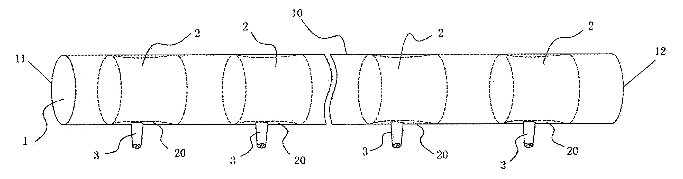
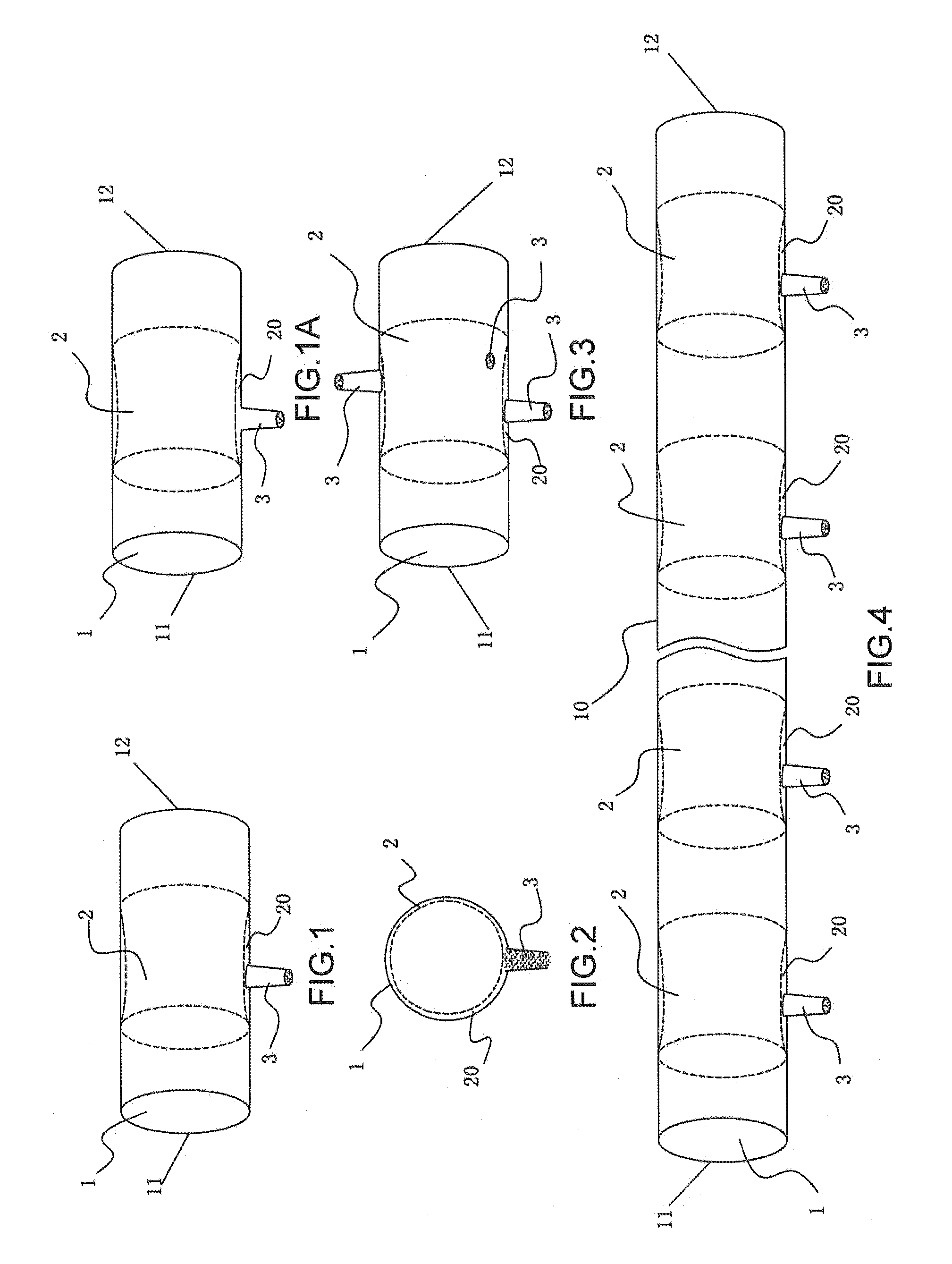
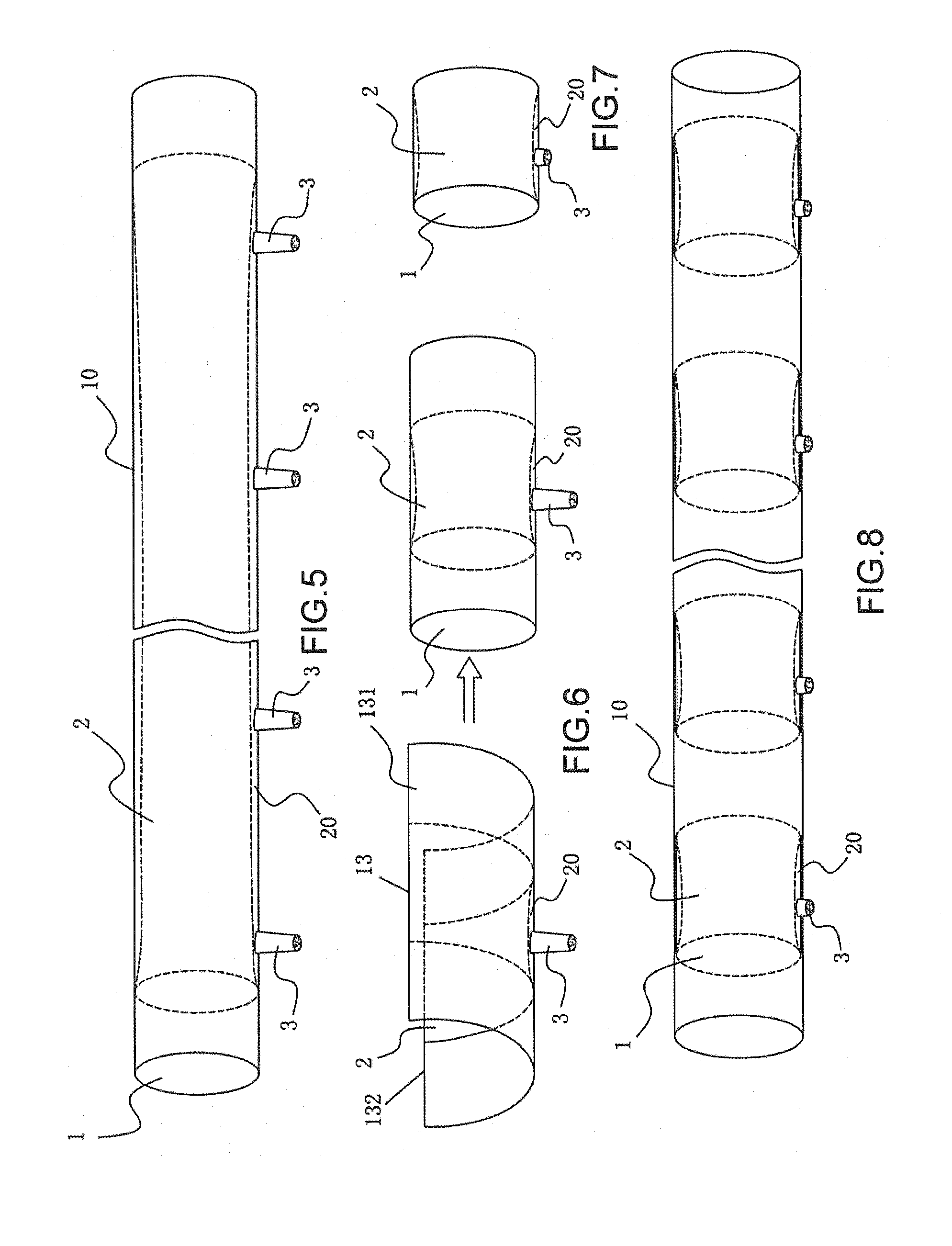
[0085]FIGS. 1 to 8 illustrate the structural diagrams of the infiltration irrigation apparatus according to Embodiment 1 of the present invention. As illustrated in FIG. 1, the infiltration irrigation apparatus according to the embodiment includes a water passing chamber 1, a porous filter membrane 2 and a flow restrictor 3. The water passing chamber 1 has a water inlet 11 and a water outlet 12. The porous filter membrane 2 covers a complete circumference of inner wall of the water passing chamber 1. The edges of both ends of the porous filter membrane 2 may closely engage with the inner wall of the water passing chamber 1 and then become waterproof, so as to form a filtration section 20 between the porous filter membrane 2 and the inner wall of the water passing chamber 1 covered thereby. The flow restrictor 3 is disposed on a sidewall of the water passing chamber 1 corresponding to the porous filter membrane 2. Each flow restrictor 3 has one or more restricting orifices, an inlet ...

embodiment 2

[0108]FIGS. 9 to 13 illustrate structural diagrams of Embodiment 2 of the present invention. The basic structure of this embodiment is substantially the same as that of Embodiment 1, the descriptions of the same portions are omitted herein, and the difference is the manner of disposing the porous filter membrane 2. In this embodiment, provided that the total water seepage capability of the porous filter membrane 2 is larger than that of the flow restrictor 3, the porous filter membrane 2 may be just disposed on a part of the circumference of the inner wall of the water pipe 1, i.e., it only covers a part of the inner circumferential wall of the water passing chamber 1 corresponding to the flow restrictor 3. In addition, the edges of the porous filter membrane 3 closely engage with the inner of the water pipe to proof water, so as to form an isolated filtration section 20 between the porous filter membrane 2 and the inner wall of the water pipe covered thereby. The water cannot becom...

embodiment 3

[0115]FIGS. 14 to 19 illustrate structural diagrams of Embodiment 3 of the present invention. The basic structure and the principle of this embodiment are substantially the same as that of Embodiment 1, and the descriptions of the same portions are omitted herein. As illustrated in FIGS. 14 to 19, this embodiment differs from Embodiment 1 in that the porous filter membrane 2 is bag-shaped, and the filtration section 20 is formed in a bag of the porous filter membrane 2. During the infiltration irrigation, the water cannot become irrigation water until it enters the bag through the bag-shaped porous filter membrane 2 (i.e., into the filtration section 20), and flows out of the tubular infiltration irrigation apparatus through the flow restrictor 3.

[0116]In addition to the effect of Embodiment 1, since a bag-shaped porous filter membrane 2 is used, a blockage is more difficult to be caused. Because firstly, as compared with the flush porous filter membrane, the bag-shaped porous filte...


PUM


Abstract

A filtration irrigation method, filtration irrigation device and the manufacturing method thereof, said filtration irrigation device comprises a water carrying chamber, in which one or more porous filter membranes are arranged. One or more flow restrictors corresponding to each membrane are set on the wall of the water carrying chamber. The total permeation capacity of the flow restrictors is less than that of said filter membranes. The present invention can avoid the blockage of the device effectively.

Description

FIELD OF THE INVENTION[0001]The present invention relates to a micro-irrigation technique for irrigating plants, and particularly, to an infiltration irrigation method, an infiltration irrigation apparatus and a method for manufacturing the same.BACKGROUND OF THE INVENTION[0002]In the drip irrigation and the infiltration irrigation at present, a most important problem is the blockage of the water outflow pores of the irrigator. In order to prevent the blockage, a common method is to perform a water treatment at the water supply end of the irrigation pipeline. However, this requires a very large investment on equipments, and the whole pipeline may be discarded due to any improper water treatment.[0003]A diameter of the drip irrigation water outflow pore is generally between 0.5 and 1 mm, and the diameter of the infiltration irrigation water outflow pore is mainly from tens of microns to more than one hundred microns. It is found upon research that the blockage is caused by many impur...

Claims


Application Information

Patent Timeline
Patent Type & Authority Applications(United States)
IPC IPC(8): B05B1/30
CPCB05B15/008A01G25/02B05B15/40Y02A40/22A01G25/00
Inventor ZHU, JUN
Owner ZHU JUN
Why Eureka
Try Eureka