

Cam-based infinitely variable transmission
- Summary
- Abstract
- Description
- Claims
- Application Information
AI Technical Summary
Benefits of technology
Problems solved by technology
Method used
Image

Examples
Embodiment Construction
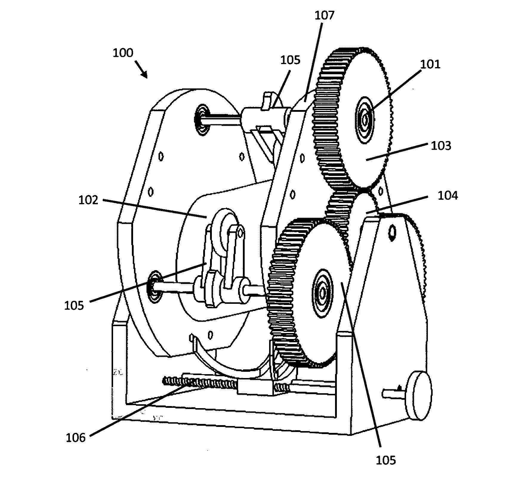
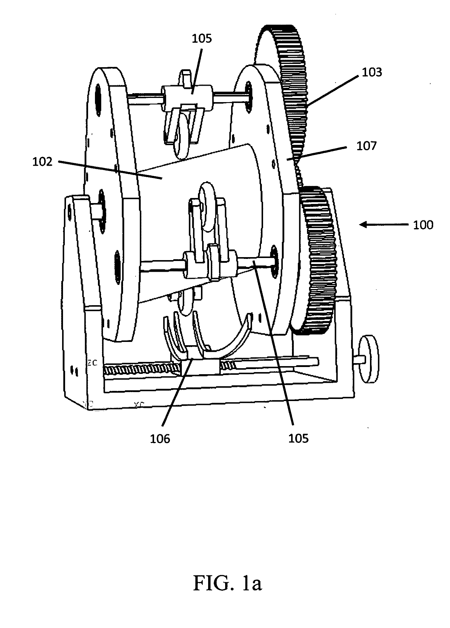
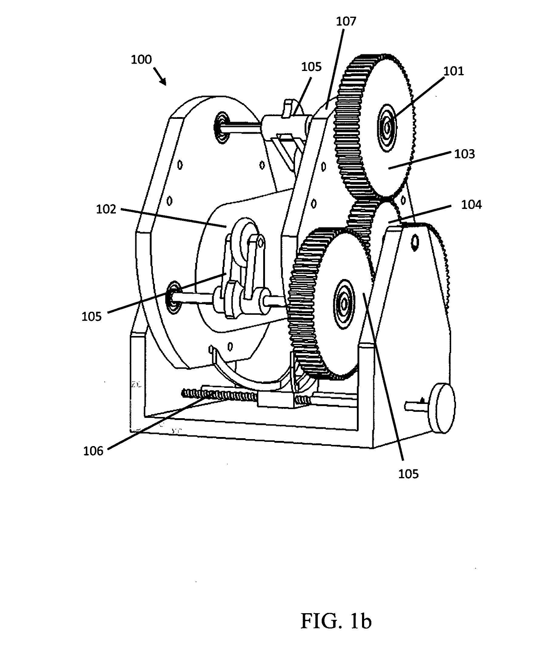
[0028]A continuously variable transmission (CVT) is a system which allows a user to vary the speed between an input and output progressively from one positive value to another. Unlike conventional transmissions, the selection of gears is not restricted to a finite number of ratios. Infinitely variable transmissions (IVTs) are CVTs which also have a transmission ration of zero. Presented here is a novel, highly configurable, ratcheting CVT / IVT based on the operation of a planetary gearset. It is unique in both its operation and its possible applications because it combines the flexibility of a planetary gearset and a CVT into one package. Unlike other ratcheting CVTs which produce a non uniform output for a uniform input, the instant invention can shape the output to match many periodic waveforms. Consequently, this ratcheting drive has the unique ability to produce a uniform and continuous output.
[0029]The instant invention has many applications. CVTs currently improve the performan...
PUM
 Abstract
Description
Claims
Application Information