Flushing valve

Active Publication Date: 2010-12-09
GTP DEV
View PDF7 Cites 3 Cited by
  • Summary
  • Abstract
  • Description
  • Claims
  • Application Information

AI Technical Summary

Benefits of technology

[0049]Employment of a diaphragm chamber provides the pressure head valve with th

Problems solved by technology

By preventing the inlet valve and the outlet valve from simultaneously being in their open positions results in the

Method used


Image

  • Flushing valve
  • Flushing valve
  • Flushing valve

Examples


Embodiment Construction

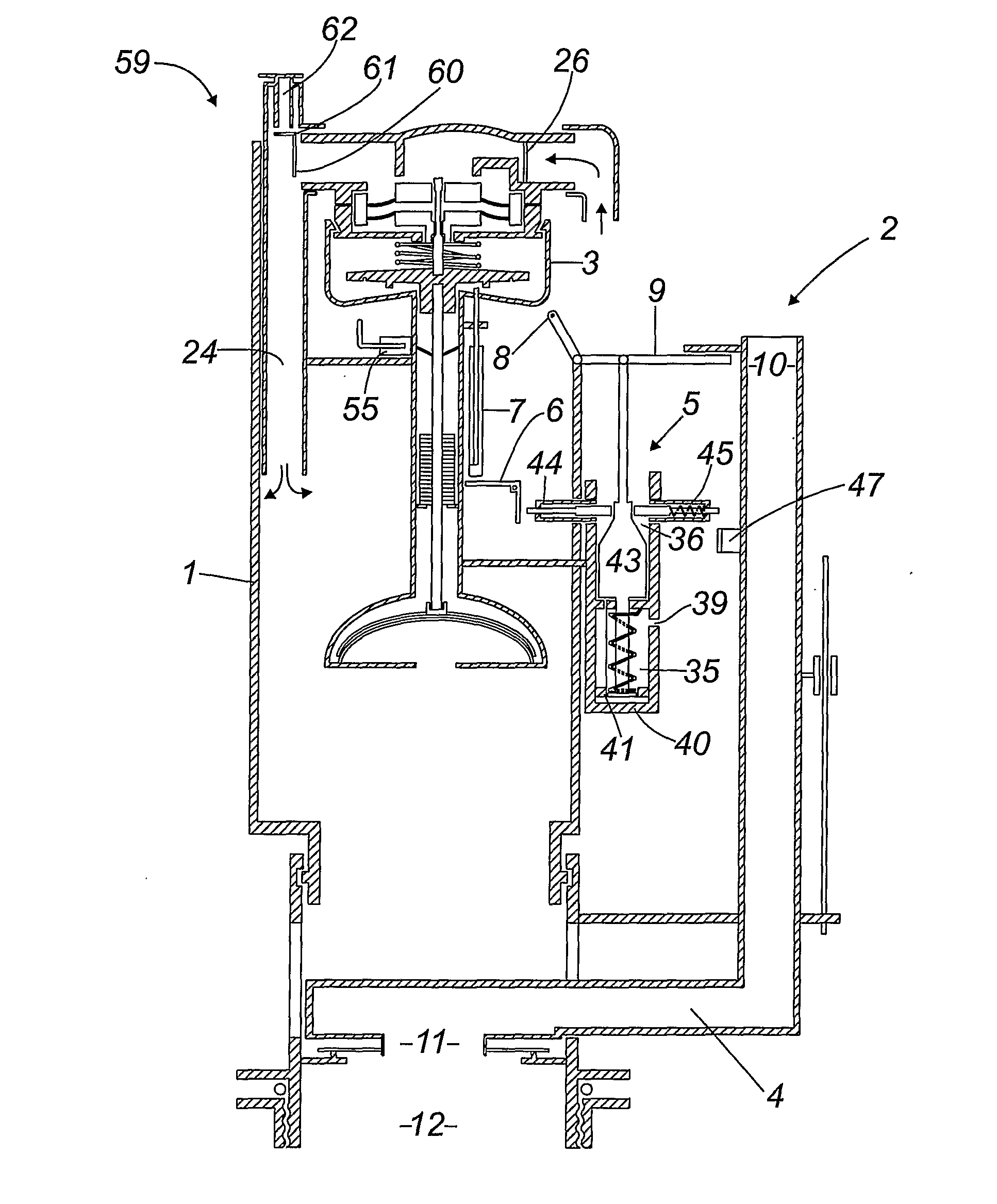
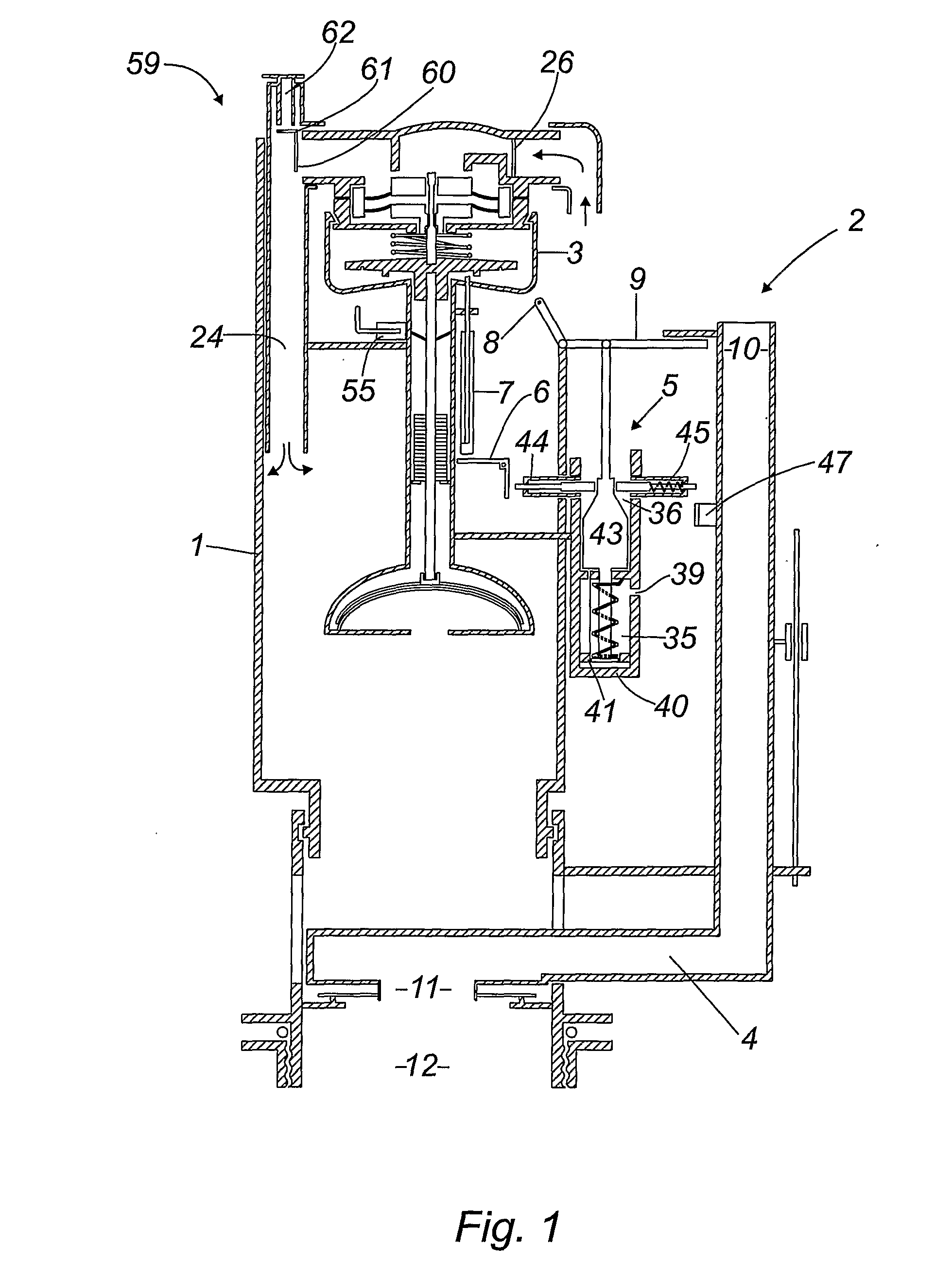
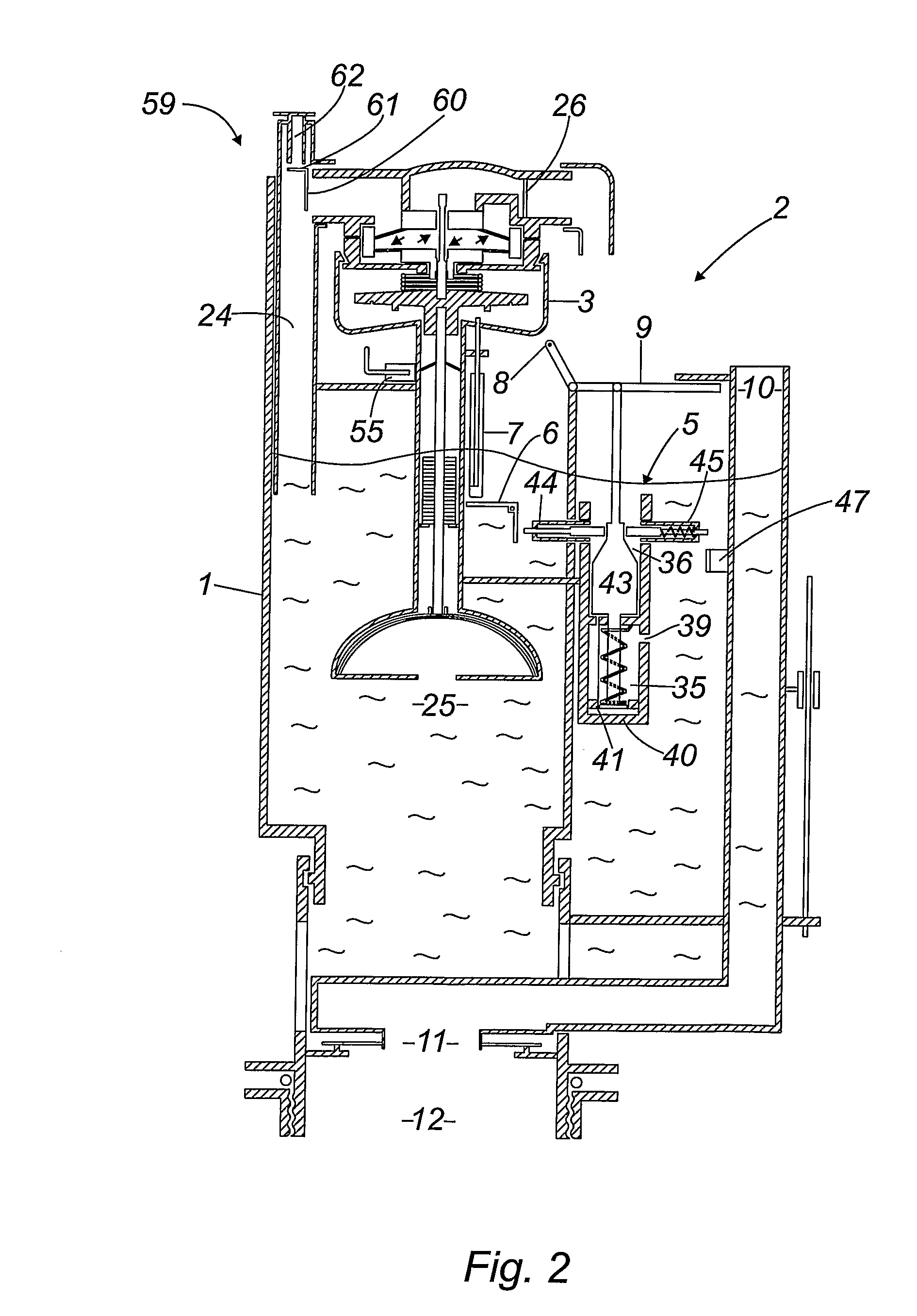
[0078]In order to assist understanding of the present invention, FIGS. 1 to 3 presents schematic diagrams of a cistern 1, comprising a flushing valve 2 in accordance with an aspect of the present invention, within three separate modes of operation. The flushing valve 1 can be seen to comprise three separate mechanically connected valves namely:[0079]1) an inlet valve 3 in the form of a double diaphragm pressure head valve;[0080]2) an outlet valve 4 in the form of a drop valve; and[0081]3) a timer valve 5 mechanically connected to both the inlet and outlet valves.

[0082]The timer valve 5 is connected to the inlet valve 3 via an L-shaped lever 6 and a first rod 7. A lever 8 mechanically connects the timer valve 5, via a second rod 9 to the overflow tube 10 of the outlet drop valve 4. The outlet drop valve 4 further comprises a plug 11, made of a rubber, for control of the opening and closing an outlet tube 12 of the cistern 1. As described in detail below, the timer valve 5 is employed...


PUM


Abstract

A flushing valve suitable for reducing water wastage from a cistern of a toilet is described. The flushing valve comprising an inlet valve, an outlet valve and a timer valve. The timer valve is mechanically connected to both the inlet valve and the outlet valve so as to control their movement between an open and a closed position such that the timer valve prevents both the inlet valve and the outlet valve from simultaneously being in their open positions. By preventing the inlet valve and the outlet valve from simultaneously being in their open positions results in the fact that the flushing valve does not allow the cistern to start to refill until after the flush process is complete. This results in a significant reduction in the volume of water passing through the cistern during each flushing cycle.

Description

[0001]The present invention relates to the field of valves and, in particular, to a flushing valve suitable for reducing water wastage from a cistern of a toilet.[0002]It is estimated that the daily flushing of toilets in the UK results in approximately 3030 million litres of water being flushed away. This value comprises around 690 million litres from domestic toilets, 480 million litres from work place toilets, and approximately 1860 million litres from toilets employed by the roaming population. As a result over three billion litres of water goes to waste or is required to be retreated each day.[0003]Toilet cisterns are typically sold as nominal six, seven, or eight litre systems. In practice however, each flush uses more than the associated nominal value because as soon as the toilet is flushed the cistern immediately starts to refill. Generally a flush is designed to allow as much water as possible to pass from the cistern into the bowl in order to carry away waste. As a result...

Claims


Application Information

Patent Timeline
IPC IPC(8): E03D1/36F16K7/00F16K1/00
CPCE03D1/36
Inventor BELL, THOMAS HENRY
Owner GTP DEV
Why Eureka
Try Eureka