Multifunctional conveying drum

a conveying drum and multi-functional technology, applied in the direction of mechanical conveyors, packaging, tobacco smoke filters, etc., can solve the problems of costly replacement of control elements and/or control cams, down time, element expense and man hours

Inactive Publication Date: 2005-06-30
HAUNI MASCHINENBAU AG
View PDF9 Cites 3 Cited by
  • Summary
  • Abstract
  • Description
  • Claims
  • Application Information

AI Technical Summary

Benefits of technology

[0008] In view of the art discussed above, it is an object of the present invention to provide a conveying drum, which subjects articles to be conveyed in the tobacco-processing industry to a low amount of mechanical stress during a longitudinal axial displacement movement, while allowing the continued use of other existing components of a machine in the tobacco-processing industry.
[0010] One embodiment of the invention includes the longitudinal axial displacement of articles on the conveying drum, where electric drives are used for staggering or moving apart such items as cigarettes, tobacco rod sections, or filters in an axial direction. In contrast to mechanical displacement devices for conveyed smoking articles, which generally include a control element, a cam roller and a push rod for the displacement element (e.g. a sliding carriage), the electric drive of one embodiment of the invention directly displaces the displacement element on the conveying device. As a result, the rods which previously required a drive for the mechanical guidance of the sliding carriages and / or the displacement members are now mounted fixedly in the drum and function exclusively as guide rods. In addition, the invention has the advantage of avoiding the problem of contamination with oil, resulting from the lubricating of the control cam and / or the cam roller.
[0011] Furthermore, the electric drive noticeably reduces the noise associated with the conveyor drum. In addition, it is no longer necessary to manually replace the control cam of the mechanical displacement element with another control cam during a format changeover. Such a replacement of control elements and / or control cams is costly with down time, element expense and man hours. The displacement movement of elements and / or the electric drive of an exemplary embodiment of the invention is realized with a simple adaptation to an electric drive and by electronically adjusting the control and adjustment device. The control and adjustment device preferably is a software oriented control device. In this embodiment, the electric drive may be provided with a electronic control device.
[0012] According to a preferred modification of the invention, the electric drive be embodied as a linear drive or a plunging coil drive. Linear drives and / or linear motors using electromagnets and rotary motors execute continuous linear movements with high precision. Direct linear drives do not comprise mechanical motion converters (e.g., control cams) so that the operation of a linear motor is low-noise and causes little wear. In addition, linear drives have a long service life and are furthermore distinguished by low moving masses, as well as low elasticity and friction. In addition, the motion transfer occurs nearly without play. As a result of these characteristics, linear motors are suitable for use in conveying drums of the tobacco-processing industry since linear drives have a high dynamic and positioning accuracy for executing displacement movements.

Problems solved by technology

Such a replacement of control elements and / or control cams is costly with down time, element expense and man hours.

Method used


Image

  • Multifunctional conveying drum
  • Multifunctional conveying drum
  • Multifunctional conveying drum

Examples


Embodiment Construction

[0023] Identical or similar elements and / or parts are provided with the same reference numbers. Accordingly, each reference numeral is described once in the following description.

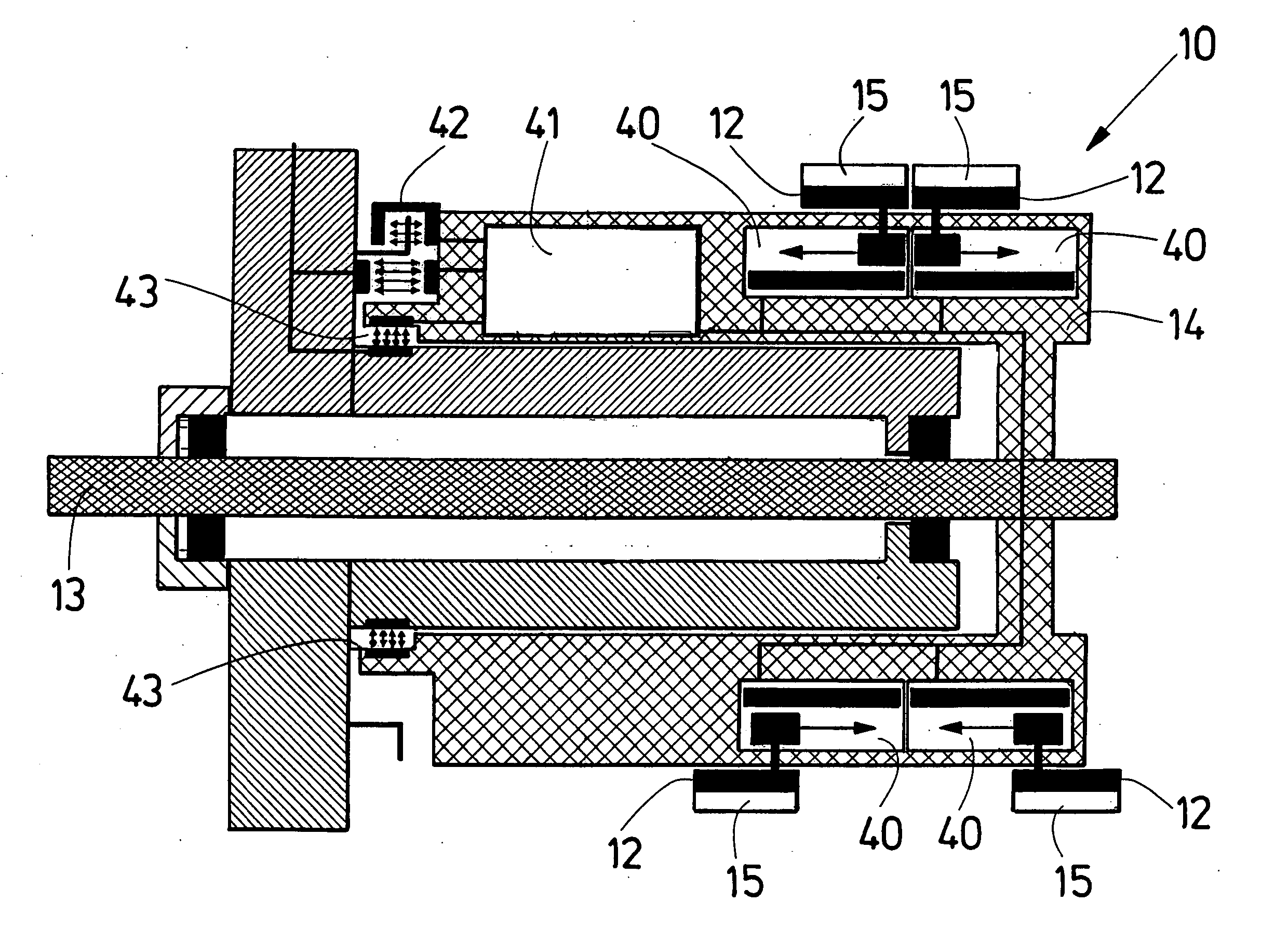
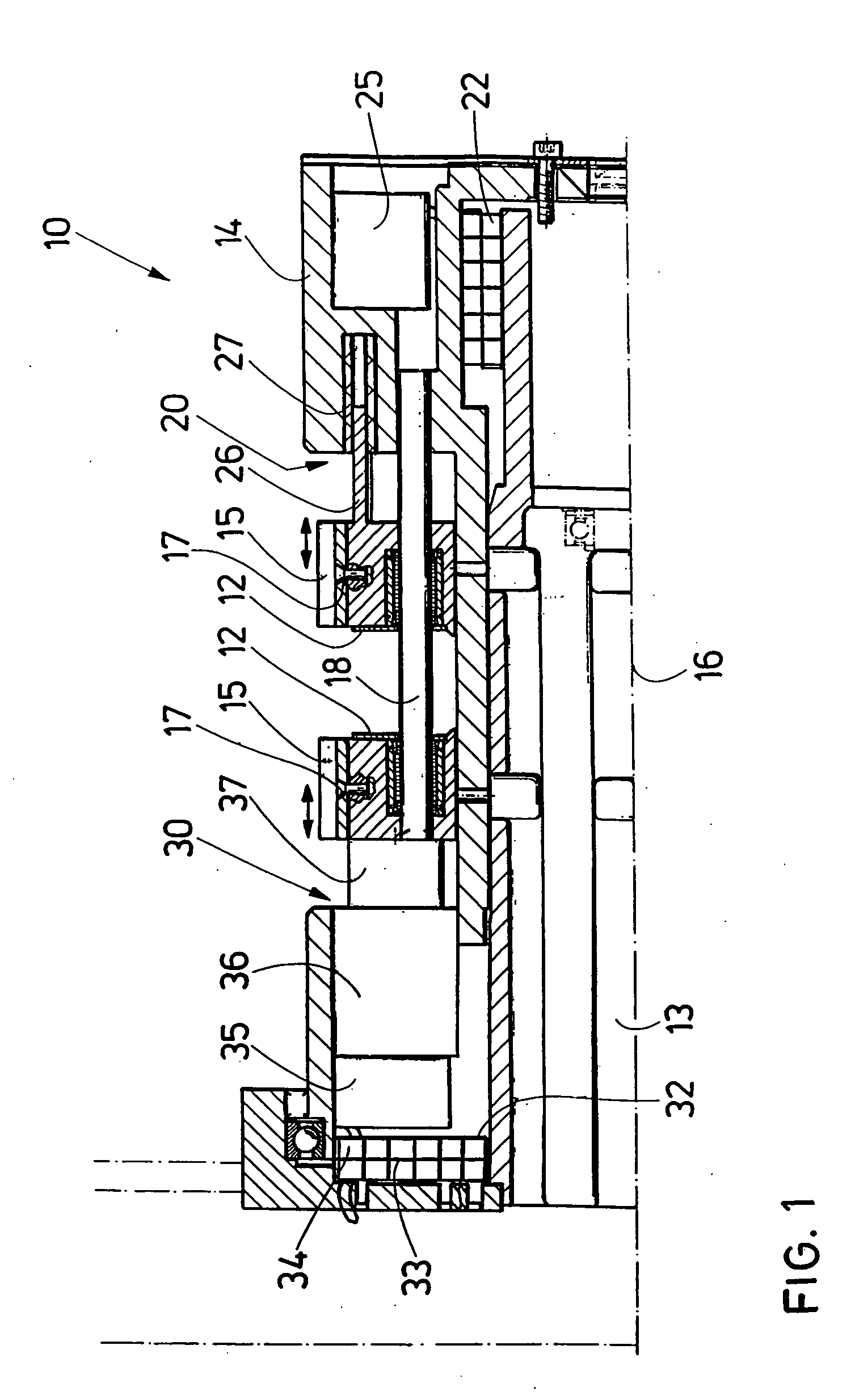
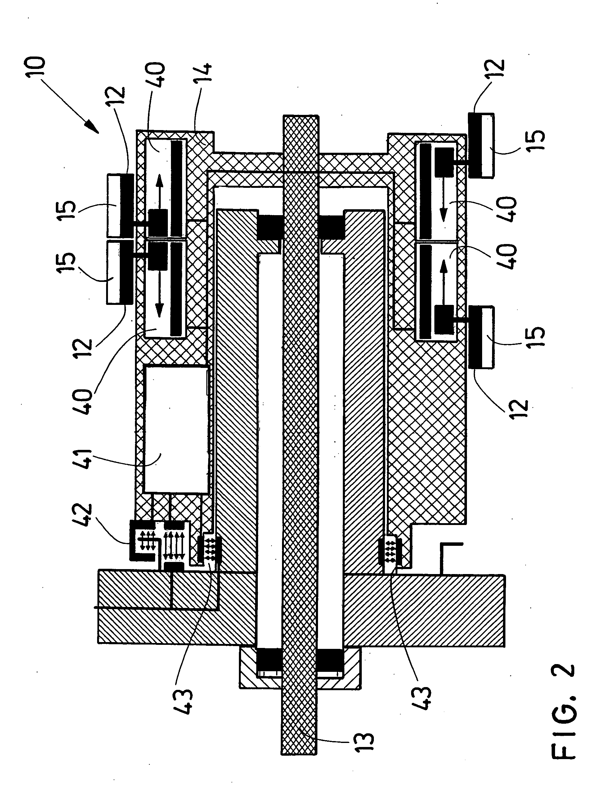
[0024]FIG. 1 shows a detail of a cross section through a conveying drum 10 with two different drives 20, 30 for respectively sliding a carriage 12, on which cigarettes 15 are placed, in a respective longitudinal axial direction. The conveying drum 10 comprises a drum body 14 which rotates around a locally fixed shaft 13 with a rotational axis 16. The sliding carriages 12 are provided with receiving troughs, preferably for receiving several cigarettes 15. The cigarettes 15 are held inside these receiving troughs in the sliding carriages 12 by means of a vacuum, generated inside the conveying drum 10 and administered through the vacuum bores 17.

[0025] To execute the displacement movements, the sliding carriages 12 are positioned on a rigid guide rod 18, such that they can be displaced. The right side of FIG...


PUM

PropertyMeasurementUnit
displacementaaaaaaaaaa
energyaaaaaaaaaa
angleaaaaaaaaaa

Abstract

The invention relates to a conveying drum for articles in the tobacco-processing industry. The conveying drum includes displacement means for moving articles, that are aligned in a longitudinal axial direction relative to each other and are supplied cross-axially in at least one row to the conveying drum, wherein the displacement means includes an electric drive. The invention furthermore relates to the use of an electric drive in a conveying drum, as well as to a machine in the tobacco-processing industry.

Description

CROSS-REFERENCE TO RELATED APPLICATION [0001] This application claims the priority of German Patent Application No. 103 49 967.9, filed on Oct. 24, 2003, the subject matter of which is incorporated herein by reference. [0002] The invention relates to a drum for conveying articles in the tobacco-processing industry, including a displacement means for articles that are aligned coaxially relative to each other and are conveyed cross-axially in at least one row to the conveying drum. The invention furthermore relates to the use of an electric drive in a conveying drum, as well as a machine in the tobacco-processing industry. [0003] Generally, articles in the tobacco-processing industry are understood to be rod-shaped objects that are held by a vacuum in one or several parallel sequences on devices for conveying the articles, for example the conveying drums of filter or cigarette makers. Articles of this type are filter cigarettes, cigars, cigarillos as well as filter rods, filter member...

Claims


Application Information

Patent Timeline
Patent Type & Authority Applications(United States)
IPC IPC(8): A24C5/14A24C5/32A24C5/33A24C5/47A24D3/02
CPCA24C5/478A24C5/327
Inventor FOLGER, MANFREDWEDEKIND, DIERKHORN, SONKE
Owner HAUNI MASCHINENBAU AG
Why Eureka
Try Eureka