Hydraulic rescue tool with quick-change head

a technology of hydraulic rescue tools and head, which is applied in the field of hydraulic rescue tools, can solve the problems of only being able to accomplish the maintenance and repair of most tools in a well equipped facility, and achieve the effects of reducing maintenance costs, reducing maintenance costs, and facilitating removal of blades

Inactive Publication Date: 2010-12-09
FIVE STAR IP HLDG
View PDF23 Cites 21 Cited by
  • Summary
  • Abstract
  • Description
  • Claims
  • Application Information

AI Technical Summary

Benefits of technology

[0019]Therefore the primary object of the invention is to provide a rescue tool that incorporates a quick-change head, thereby permitting the tools hydraulic cylinder to remain attached to the power source and only the portion having the operable cutting blades removed. Incorporating a separable head within the body of the hydraulic cylinder makes the removal of the blade easy by simply disconnecting quick release pins and sliding two of the main structural members apart. By having other specialized heads with blades such as spreaders or specific purpose implements, the rescue personnel has greater flexibility while still using the same basic tool.
[0020]An important object of the invention is that a spare head with the cutting blades attached may be stored with the rescue tool, thus making the change rapid and easily accomplished.
[0021]Another object of the invention is that the quick release pins are tethered to either the cylinder body or the head, which prevents loss and provides a rapid change without fumbling or misplacing the pin in an emergency situation.
[0022]Still another object of the invention is that the cost of a spare or specialized removable head is considerably less than an entire standby tool.

Problems solved by technology

Common rescue tools basically function in their given task but most tools require maintenance and repair which can only be accomplished in a well equipped facility.
If a blade is broken or some other major malfunction occurs in the field, the emergency personnel must disconnect the tool and quickly find a replacement blade, which may not always be available.

Method used


Image

  • Hydraulic rescue tool with quick-change head
  • Hydraulic rescue tool with quick-change head
  • Hydraulic rescue tool with quick-change head

Examples


Embodiment Construction

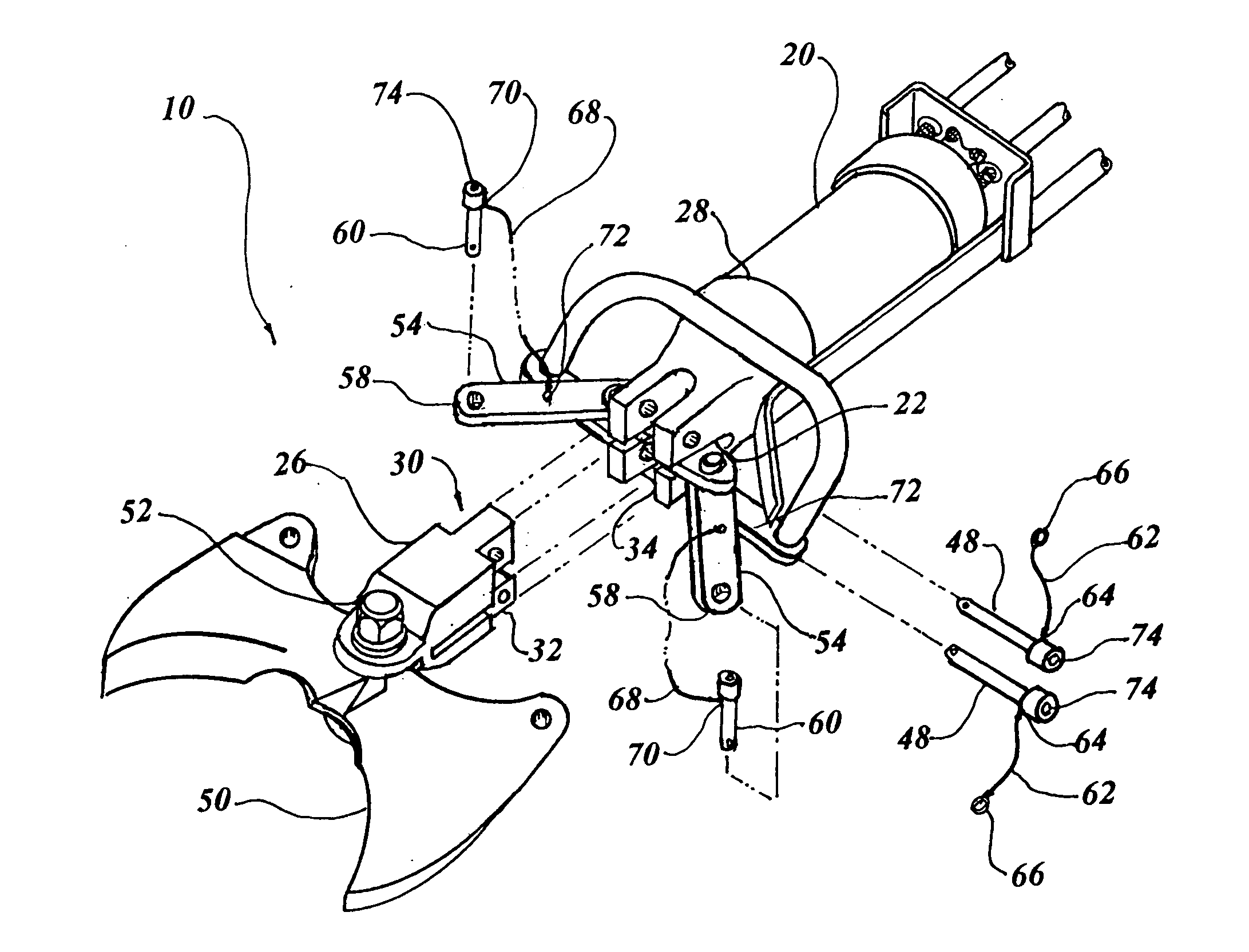
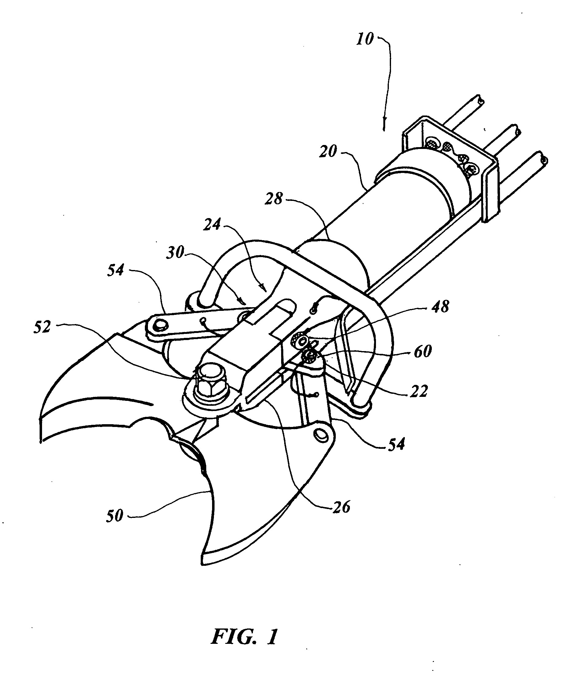
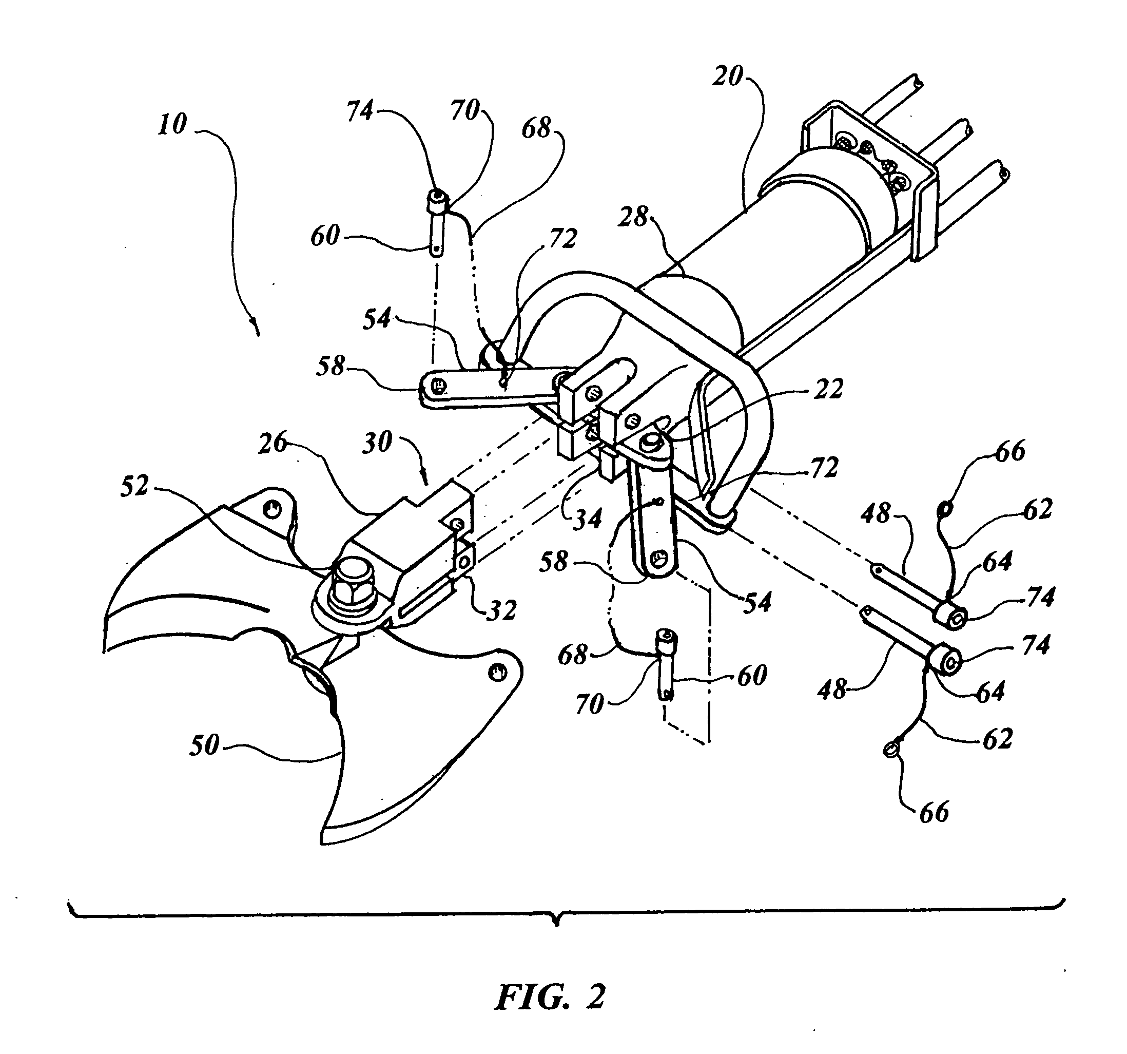
[0035]The best mode for carrying out the invention is presented in terms of a preferred embodiment of a hydraulic rescue tool that features a quick-change head 10. The preferred embodiment, as shown in FIGS. 1 through 9, is comprised of a cylinder 20 having a piston rod 22 and a forward end structure 24. The forward end structure 24 has a separable head 26 and a cylinder attaching bifurcated yoke 28, as illustrated in FIGS. 1 through 3.

[0036]The head 26 and yoke 28 can be easily and quickly disconnected by utilizing any of the following alternatives: a tongue and groove 30, as shown in FIGS. 4 and 5, with the tongue 32 in FIG. 4 and the groove 34 in FIG. 5; a pin and socket 36 depicted in FIGS. 6 and 7, with the pin 38 in FIG. 6 and the socket 40 in FIG. 7; or a dovetail 42 as illustrated in FIGS. 8 and 9, with an attachment pin 44, as shown in FIG. 8 and a tail 46, as shown in FIG. 9. However, the method of separating the head 26 from the yoke 28 is not limited to any one of the th...


PUM

PropertyMeasurementUnit
speedsaaaaaaaaaa
temperatureaaaaaaaaaa
lengthaaaaaaaaaa

Abstract

A hydraulic rescue tool (10) with a quick-change head (26) that incorporates a cylinder (20) having a piston rod (22) and a forward end structure (24). The forward end structure (24) has a separable head and a cylinder attaching bifurcated yoke (28). A pair of yoke quick release pins (48) jointly engage the head (26) and the bifurcated yoke (28) thus, creating an attachment therebetween. A pair of cutting blades (50) are connected to the head (26), and links (54) connect to the piston rod on a first end and to the cutting blades (50) on a second end, thereby forcing the cutting blades from an open position to a closed position by movement of the piston rod (22). A pair of link quick release pins (60) engage the links (54), creating an attachment therebetween, permitting the links to be released by manually disengaging the quick release pins, thereby allowing the head, including the cutting blades, to be rapidly removed or repaired.

Description

CROSS REFERENCE TO RELATED APPLICATION[0001]This application claims priority of Provisional Application No. 61 / 127,276 filed May 13, 2008. and International Application PCT / US09 / 02941 filed 12 May 2009.TECHNICAL FIELD[0002]The invention generally pertains to hydraulic rescue tools, and more particularly to a detachable head for a rescue tool that includes cutting blades allowing the head to be rapidly removed and replaced with the same or alternative types of blades or to easily repair the existing blades.BACKGROUND ART[0003]For any person who works in an occupation that is responsible for rescuing and / or saving victims of accidents, their tools are often the only means by which to actually save a person's life. One of the most effective and widely used tools for rescuing a person is the “Jaws of Life”® type device. This device, of which there are several different design configurations, and can be powered by different means as well, are used to free a trapped and often injured vict...

Claims


Application Information

Patent Timeline
Patent Type & Authority Applications(United States)
IPC IPC(8): B23D29/00B26B15/00
CPCA62B3/005B23D17/00B23D17/06B26B15/00B23D35/002B26B13/04B23D31/008
Inventor PATTON, TOMMY L.HAGBLOOM, EDWARD H.
Owner FIVE STAR IP HLDG
Why Eureka
Try Eureka