Refrigeration system

a technology of refrigerant and valve, which is applied in the direction of fluid circulation arrangement, evaporator/condenser, light and heating apparatus, etc., can solve the problems of inferior importance, and achieve the effect of keeping the flow resistance of refrigerant small and opening the valv

Inactive Publication Date: 2010-12-09
DANFOSS AS
View PDF16 Cites 7 Cited by
  • Summary
  • Abstract
  • Description
  • Claims
  • Application Information

AI Technical Summary

Benefits of technology

[0010]Preferably, the valve elements are radially movable in relation to the rotation axis of the rotor. Thus, the effect of the radially directed projection can immediately be converted to a movement of the valve element. This simplifies the design of the distributor. When the valve elements are radially movable, more room is available for arranging the valve elements.
[0014]Preferably, the cage insert is arranged in the outlet opening by means of press fit. This permits a relatively simple manufacturing. The preassembled cage insert with return spring and valve element is simply pressed into the outlet opening of the housing. The frictional forces thus occurring will be sufficient to hold the cage insert in the housing. The forces acting upon the cage insert are relatively small anyway. When the valve element is open, they are made up of the force of the return spring and the pressure with which the refrigerant acts upon the valve element.
[0015]Preferably, a tappet is arranged between the rotor and each valve element. The tappet forms a transfer element between the rotor and the valve element. This makes it possible with a small rotor also to activate valves, when they are arranged on a larger radius. This gives the opportunity of providing a sufficient number of valves. Further, a larger design freedom is achieved.
[0016]It is preferred that the tappet has a length, which is smaller than a distance between the valve element bearing on the valve seat and the rotor outside the projection. Thus, with closed valve a play exists between the tappet and the rotor. Thus, it can be ensured that at any rate the valve will remain closed, when the tappet is not acted upon by the radial projection of the rotor. This play can be dimensioned so that in the total temperature area that is permitted for the distributor, it is ensured that the valves close safely.
[0019]Preferably, the ends of the tappets facing the individual valve element have a diameter reduction. Thus, over the largest part of its length the tappet can be provided with a sufficiently large diameter, so that it can adopt the pressure forces which are transferred by the projection of the rotor to the individual valve element. When its end tapers, then it is able to penetrate so far through the opening on whose outside the valve seat is formed. Thus, it is possible to open the valves sufficiently to keep the flow resistance for the refrigerant small.
[0020]Preferably, each valve element is made with a cone shape. Thus, a sealing between the valve seat and the valve element can easily be achieved. Further, the valve element can be led somewhat through the opening at whose outside the valve seat is formed, so that it can easily be reached by the tappet.

Problems solved by technology

It is also of inferior importance, if the evaporators have to provide different refrigeration performances.

Method used


Image

  • Refrigeration system
  • Refrigeration system
  • Refrigeration system

Examples


Embodiment Construction

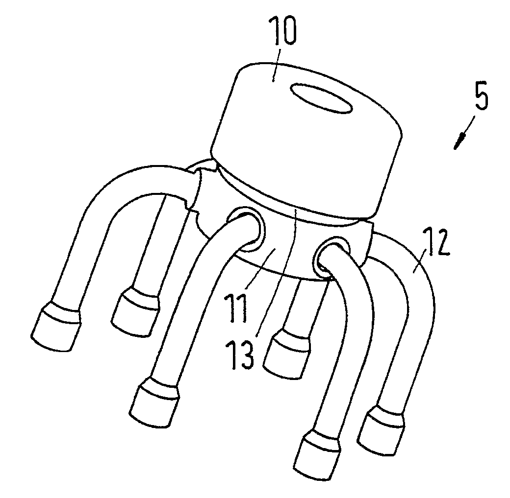
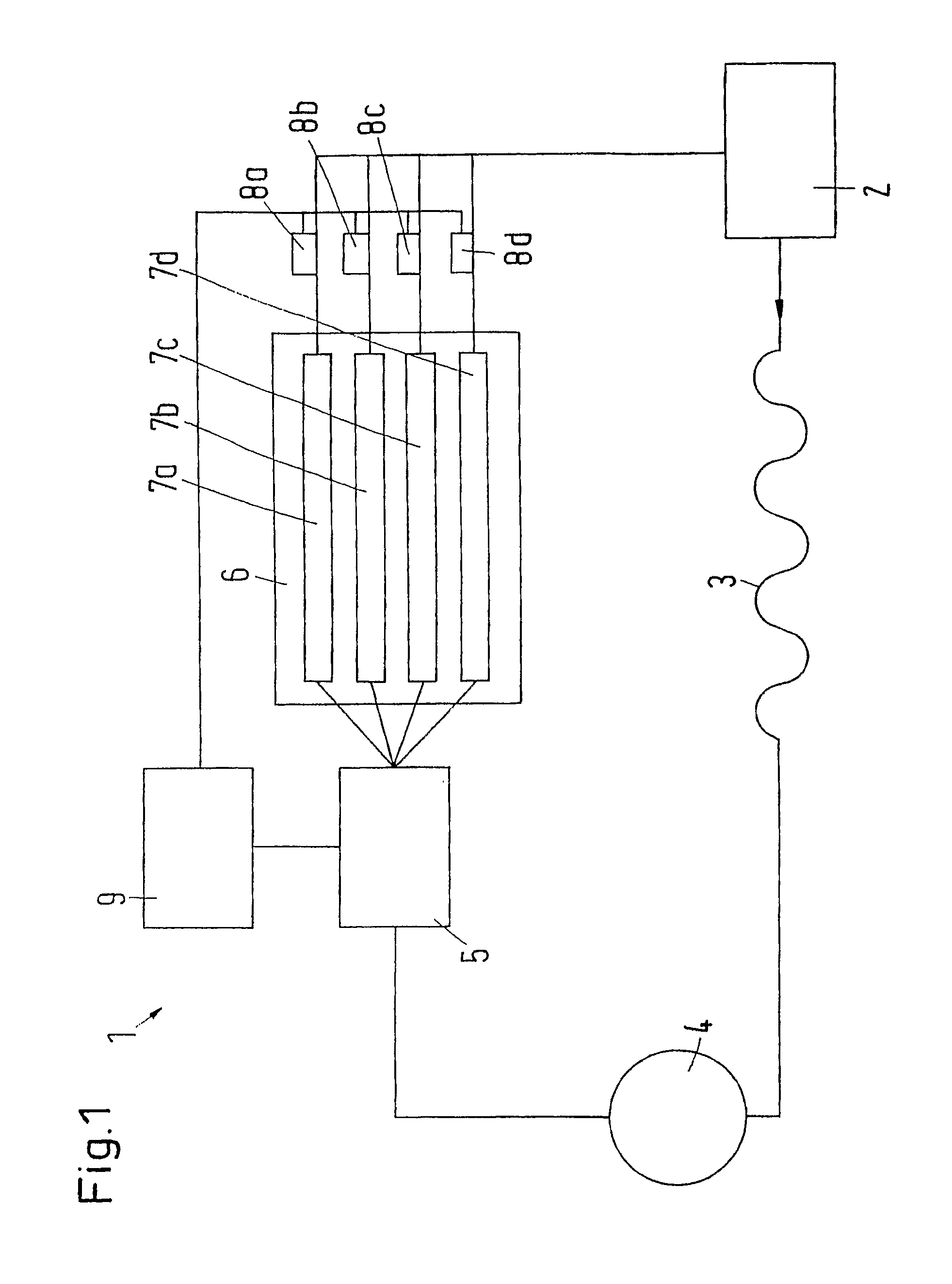
[0029]FIG. 1 is a schematic view of a refrigeration system 1, in which a compressor 2, a condenser 3, a collector 4, a distributor 5 and an evaporation arrangement 6 with several evaporators 7a-7d arranged in parallel are joined to a circuit. The evaporator arrangement 6 can also comprise one single evaporator with several evaporation paths which are controlled individually or in groups. It is also possible to provide the evaporator arrangement 6 with several evaporators, of which at least one has several evaporator paths.

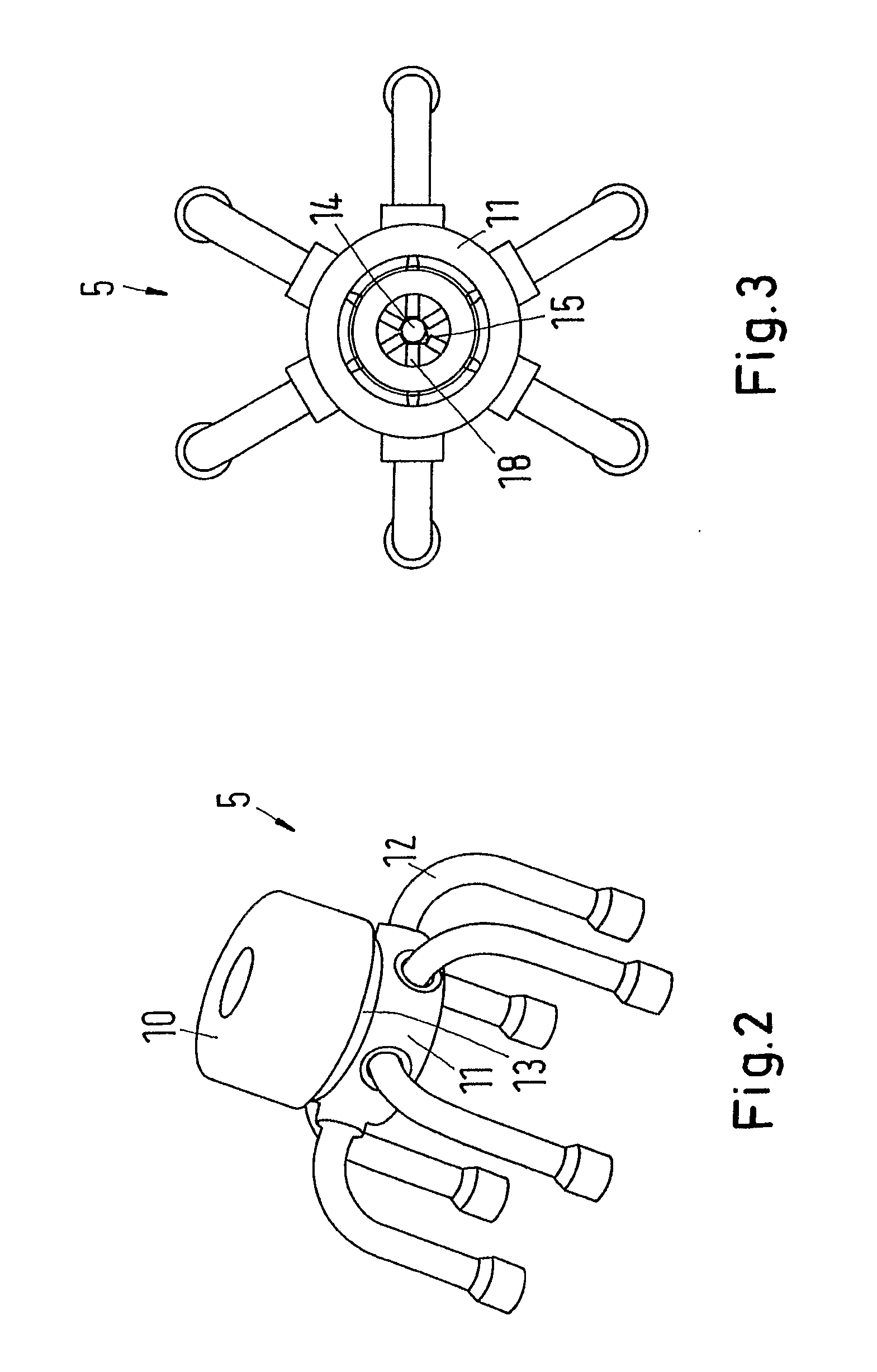
[0030]In a manner known per se, liquid refrigerant evaporates in the evaporators 7a-7d, is compressed by the compressor 2, liquefied in the condenser 3 and collected in the collector 4. The distributor 5 is provided to distribute the liquid refrigerant to the individual evaporators 7a-7d.

[0031]A temperature sensor 8a-8d is arranged at the outlet of each evaporator 7a-7d. The temperature sensor 8a-8d determines the temperature of the refrigerant leaving the evapora...


PUM


Abstract

The invention relates to a refrigeration system comprising a refrigerant circuit provided with a plurality of evaporator paths and a distributor (5) for distributing refrigerants to the evaporator paths, said distributor comprising a controllable valve (14) for each evaporator path. The aim of the invention is to enable the refrigeration system to be operated as desired using simple means. To this end, the distributor (5) comprises a housing (11) and a rotor which is rotatably mounted in the housing (11) and comprises at least one radially oriented projection (15) on the circumference thereof, which interacts respectively with a valve element of a valve.

Description

CROSS REFERENCE TO RELATED APPLICATIONS[0001]This application is entitled to the benefit of and incorporates by reference essential subject matter disclosed in International Patent Application No. PCT / DK2008 / 000222 filed on Jun. 17, 2008 and German Patent Application No. 10 2007 028 562.2 filed Jun. 19, 2007.FIELD OF THE INVENTION[0002]The invention concerns a refrigeration system with a refrigerant circuit, comprising several evaporator paths and a distributor causing a distribution of refrigerant to the evaporator paths, said distributor having a controllable valve for each evaporator path.BACKGROUND OF THE INVENTION[0003]Such a refrigeration system is known from DE 195 47 744 A1. The known refrigeration system comprises one single compressor and one single condenser, but two evaporators, which are made separately from one another. The refrigerant flow delivered by the compressor is divided into two partial flows after the condenser and before the expansion valves by means of a 3 / ...

Claims


Application Information

Patent Timeline
Patent Type & Authority Applications(United States)
IPC IPC(8): F25B1/00F25B41/06
CPCF25B39/028F25B2600/2511F25B2500/01F25B41/48
Inventor PETERSEN, HANS KURTMOUSTGAARD, ALLAN JUHLHOLST, JOERGEN
Owner DANFOSS AS
Why Eureka
Try Eureka