
Vessel to Condition Dry Drill Cuttings

a technology of dry drilling cuttings and conditioned valves, which is applied in the field of processing cuttings, can solve the problems of far fewer methods known in the field of processing the generated dry drilling cuttings

Active Publication Date: 2010-12-09
NAT OILWELL VARCO LP
View PDF28 Cites 7 Cited by
  • Summary
  • Abstract
  • Description
  • Claims
  • Application Information

AI Technical Summary

Benefits of technology

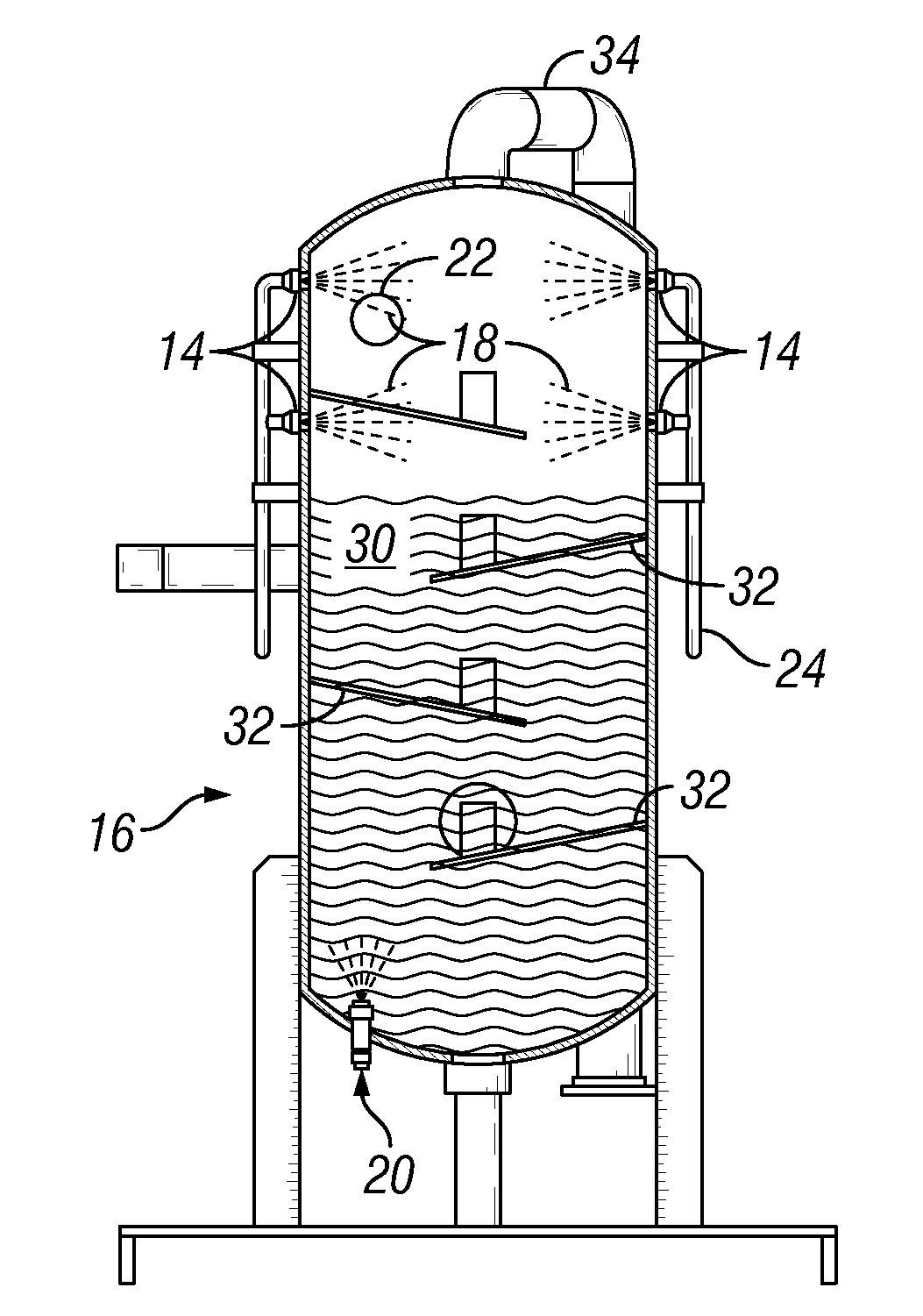
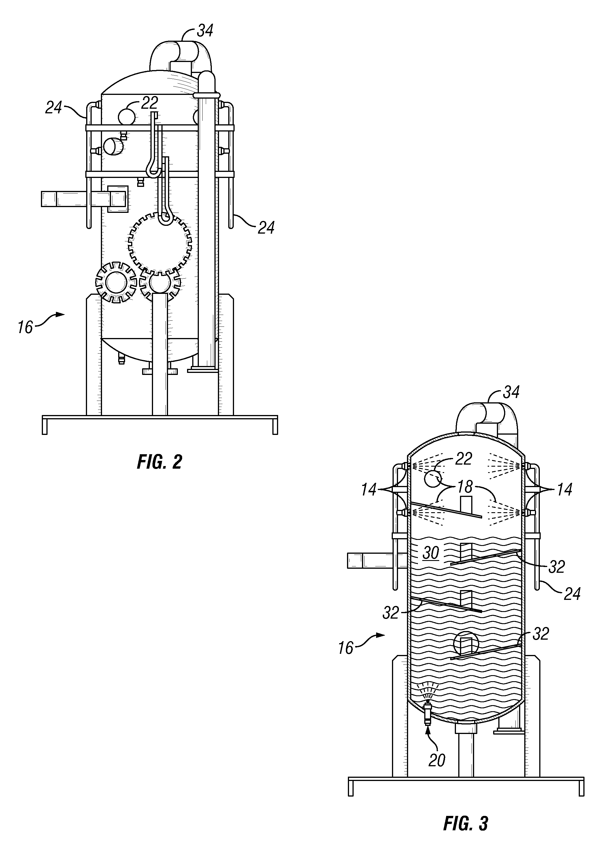
[0011]Each fluid supply ring has a number of injection nozzles spaced around the inside circumference of the vessel between its upper end and its lower end to wet the earthen drilling cuttings so that gravity aids the separation into the liquid slurry and the gas.

Problems solved by technology

However, far fewer methods are known in the field of processing the dry drilling cuttings generated when using gaseous drilling fluids, while using a wet cuttings treatment process to dispose of them.

Method used


Image

  • Vessel to Condition Dry Drill Cuttings
  • Vessel to Condition Dry Drill Cuttings
  • Vessel to Condition Dry Drill Cuttings

Examples


Embodiment Construction

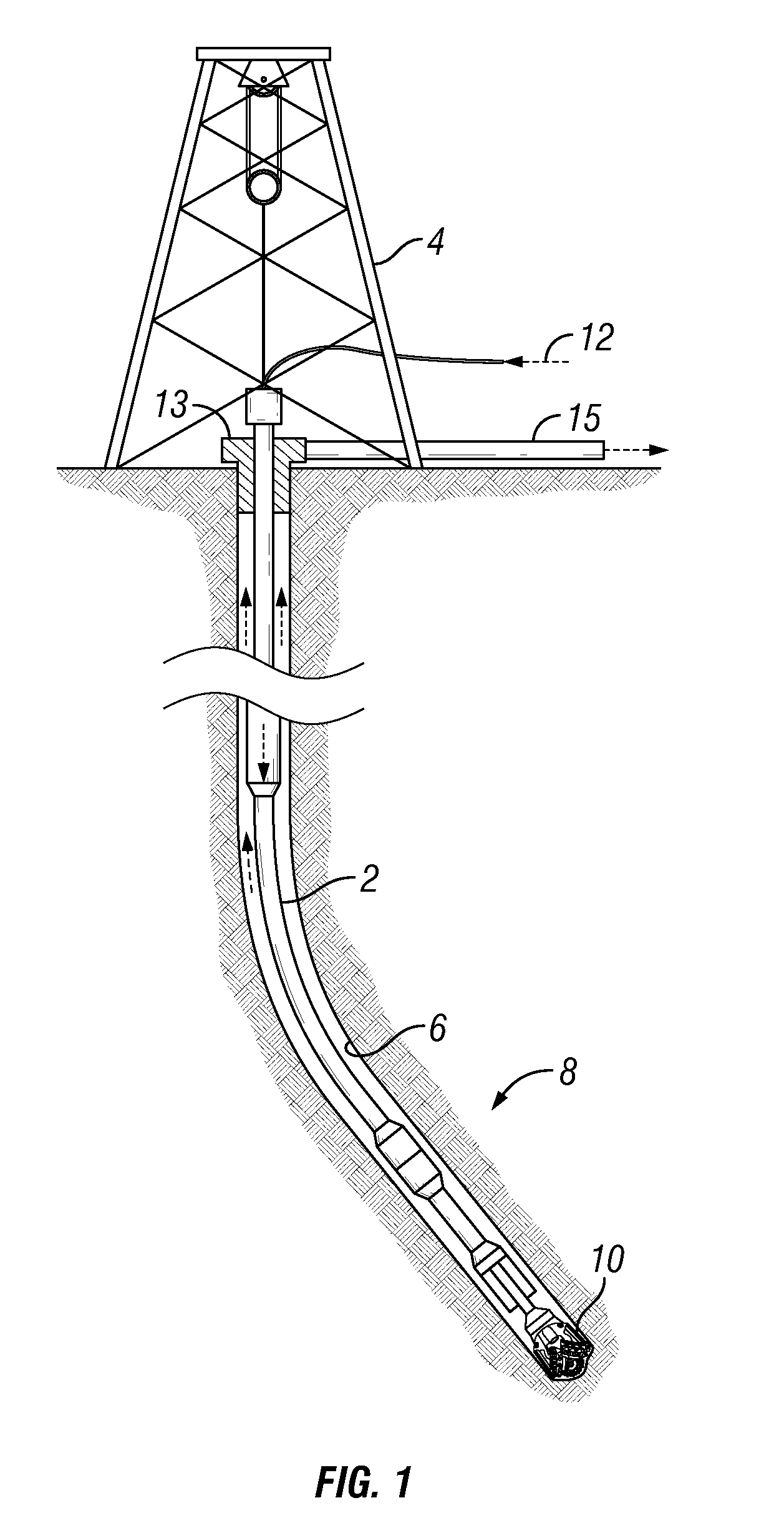
[0018]FIG. 1 shows a drill rig which uses air or other gaseous fluids to flush the drilled cuttings to the surface. The rig typically comprises a mast 4 (sometimes called a derrick) which suspends a drill string 2 in a well bore 6. Downhole tools 8 may be in the drill string 2 for making measurements and the like, and finally includes a drill bit 10 which performs the actual drilling. An air supply line 12 provides gaseous drilling fluid under pressure to flush cuttings from the drill bit 10 up the annulus of the well bore 6 and out a discharge line 15, commonly known as a “Blouie line”. The “Blouie line”15 carries the earth cuttings to a generally cylindrical treatment vessel 16.

[0019]In one aspect of the invention multiple ‘rings’14 having a plurality of injection nozzles 18 spaced around the inside circumference near the top end of the treatment vessel 16. The vessel 16 is typically mounted on its end so that gravity aids the separation process. Each ring 14 may be separately and...


PUM

PropertyMeasurementUnit
diameteraaaaaaaaaa
diameteraaaaaaaaaa
gravityaaaaaaaaaa

Abstract

Dry earthen material from an oil / gas well drilling rig is injected into an elongated vessel with a number of rings of nozzles that are arranged in conjunction with a number of water and / or chemical spray nozzles and a baffling system to knock the air / gas out of the cuttings and vent it. A relatively thick muddy waste is produced which may be easily disposed of.

Description

[0001]This application claims priority from U.S. provisional patent application Ser. No. 61 / 183,766, filed on Jun. 3, 2009, which is incorporated herein by reference.BACKGROUND OF THE INVENTION[0002]1. Field of the Invention[0003]This invention relates to the processing of the cuttings when drilling for hydrocarbons using a gaseous drilling fluid.[0004]2. Description of the Related Art[0005]It is well known there are many methods in the area of processing for ‘normal’ oil & gas well earthen and drilling fluid laden drilling mud when using a liquid drilling fluid. However, far fewer methods are known in the field of processing the dry drilling cuttings generated when using gaseous drilling fluids, while using a wet cuttings treatment process to dispose of them.[0006]However, certain drilling applications require that all or part of an oil and gas well be drilled with compressed air or other gaseous drilling fluid, say for example, nitrogen or natural gas, used as the lifting medium f...

Claims


Application Information

Patent Timeline
Patent Type & Authority Applications(United States)
IPC IPC(8): E21B21/07E21B21/06B01D19/00
CPCB09C1/02
Inventor LARGENT, DAVID
Owner NAT OILWELL VARCO LP
Learn More