Structure Of The Knife Set Of The Shredder

a shredder and knife technology, applied in the field of improved structure of the shredder knife set, can solve the problems of increasing the power demand of the shredder, difficult manufacturing, and high cost, and achieve the effects of reducing manufacturing cost, reducing weight, and being easy to manufactur

Inactive Publication Date: 2010-12-09
WANG TIE JIUN
View PDF9 Cites 0 Cited by
  • Summary
  • Abstract
  • Description
  • Claims
  • Application Information

AI Technical Summary

Benefits of technology

[0004]The objective of this invention is to provide a structure of the knife set of the shredder to achieve the effect of making a knife set which is easy to be made, lower manufacturing cost, lighter in weight and less energy needed in operation. For achieving said objective, the invention is an improvement of the structure of the knife set of the shredder, including one frame, at least two corresponding and mobile knife-rod set on said frame; in addition, each knife-rod has one hollow part respectively and multiple cutters pierce-through set on the outer edge of each knife-rod respectively.

Problems solved by technology

Although aforementioned conventional knife set can cooperate with the shredder to proceed paper-shredding process, said knife-rod which is a solid column made by cutting a metal rod is not easy to be manufactured and the cost will be higher and heavier in weight because of metal material.
Moreover, in operation, the weight of metal rod will increase the power demand of the shredder and the shredder may not run smoothly or even be damaged because of long term heavy press caused by knife-rod.
Hence, cutters of conventional shredders cannot meet the requirement of practical manufacture and operation.

Method used


Image

  • Structure Of The Knife Set Of The Shredder
  • Structure Of The Knife Set Of The Shredder
  • Structure Of The Knife Set Of The Shredder

Examples


Embodiment Construction

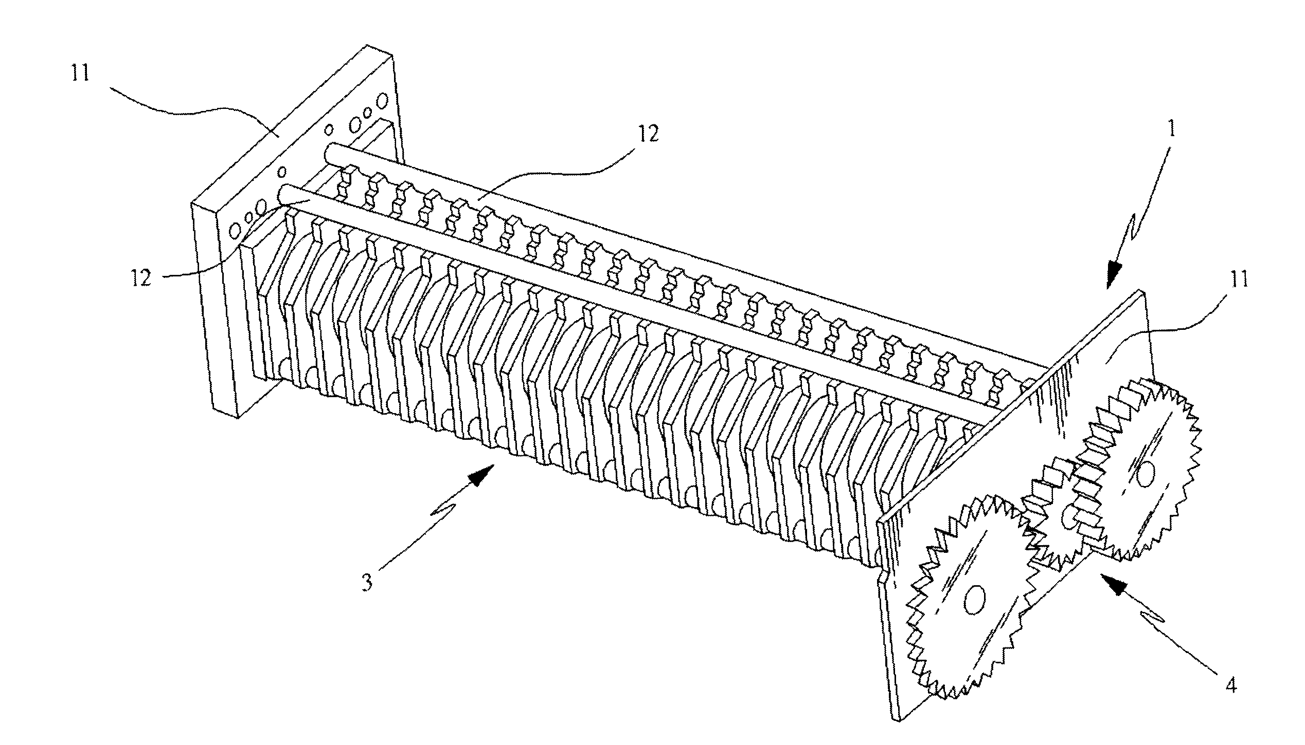
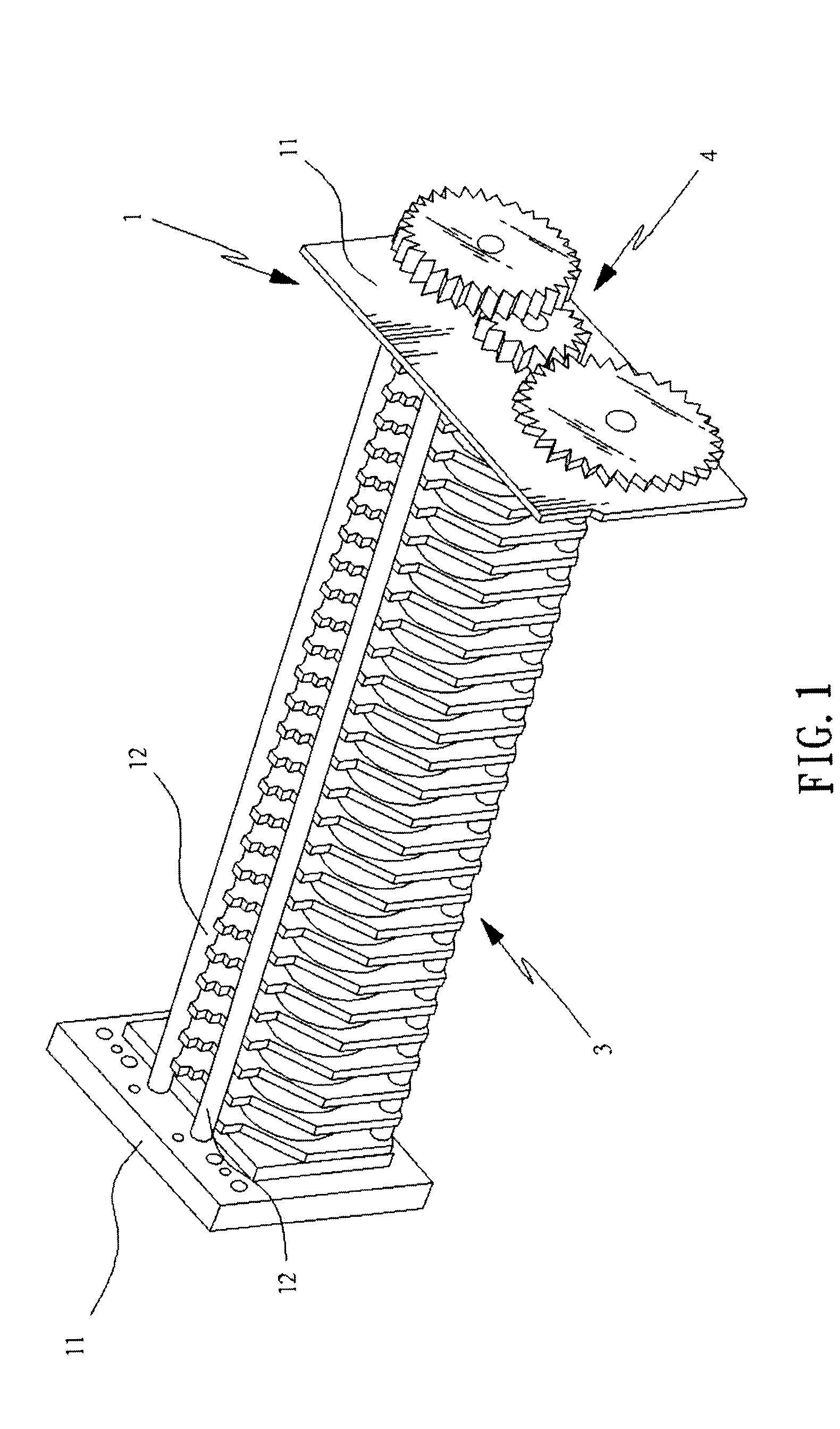
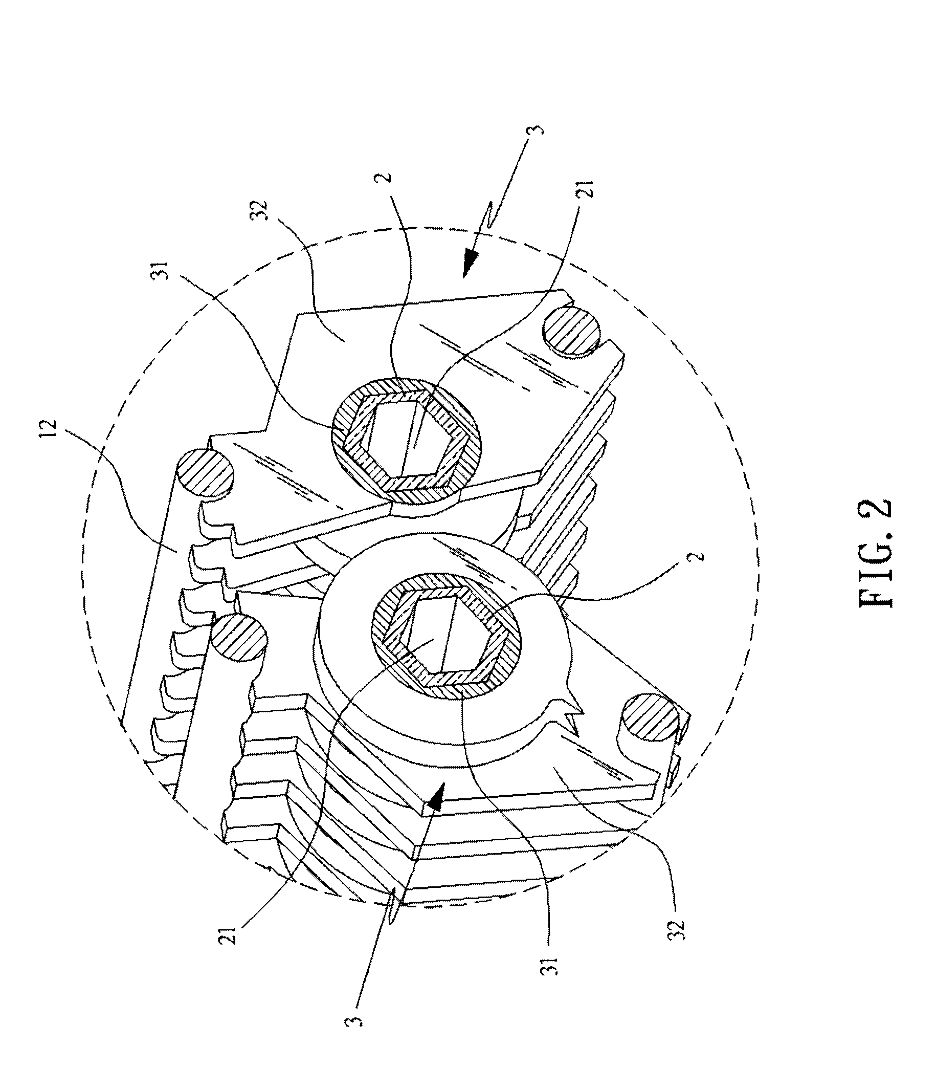
[0007]Firstly, referring to fig land 2, they are a 3-D exterior schematic view of the invention and a A-A cross-section view of FIG. 1 of the invention respectively. As the figures show that the invention is a structure improvement of the knife set of a shredder, and said structure is composed of a frame 1, at least two knife-rod 2 and multiple cutters 3.

[0008]Said frame 1 is at least composed of two side plates 11 and multiple support rod 12 set between said two side plates 11.

[0009]Each knife-rod 2 is respectively corresponding to each other and mobile set on said frame 1, and each knife-rod has a hollow part 21 respectively; at which, outer edge of each knife-rod 2 can be round shape, polygon or ratchet shape. The invention takes polygon as the preferred embodiment.

[0010]Each cutter 3 is pierce through set on outer edge of said each knife-rod and each cutter 3 at least includes knife-ring 31 for piercing through set on knife-rod 2 and blade 32 surrounding set the outer edge of kn...


PUM


Abstract

The present invention concerns an improvement of the structure of the knife set of the shredder, including one frame, at least two knife-rods corresponding to each other and mobile set on said frame; in addition, each knife-rod has one hollow part respectively and multiple cutters pierce-through set on the outer edge of each knife-rod respectively. Rely on said structure to achieve the effect of making a knife set which is easy to be made, lower manufacturing cost, lighter in weight and less energy demand in operation.

Description

FIELD OF THE INVENTION[0001]This invention relates to an improved structure of the knife set of the shredder; especially for the structure to achieve the effect of making a knife set which is easy to be made, lower manufacturing cost, lighter in weight and less energy demand in operation.DESCRIPTION OF THE PRIOR ART[0002]The knife set of a conventional shredder includes one support rack, at least two mobile knife-rods set on the support rack and multiple cutters set on the knife-rod; at which said knife-rod is normally a metal rod. When manufacturing the knife-rod, said metal rod is cut into a solid column by related mechanical tools to support multiple cutters. By means of said metal rod, said knife set structure can be set on one end of the shredder to proceed the process of shredding papers.[0003]Although aforementioned conventional knife set can cooperate with the shredder to proceed paper-shredding process, said knife-rod which is a solid column made by cutting a metal rod is n...

Claims


Application Information

Patent Timeline
Patent Type & Authority Applications(United States)
IPC IPC(8): B02C7/12
CPCB02C18/18B02C18/0007
Inventor WANG, TIE-JIUN
Owner WANG TIE JIUN
Why Eureka
Try Eureka