Wind-power generating device with automatic adjustment to wind direction

Inactive Publication Date: 2010-12-09
JETPRO TECH
View PDF3 Cites 18 Cited by
  • Summary
  • Abstract
  • Description
  • Claims
  • Application Information

AI Technical Summary

Benefits of technology

[0009]The present invention is to provide a wind-power generating device with automatic adjustment to wind direction. With an outer curved surface being blown by wind, a wind-guiding shroud can rotate with automatic adjustment to the wind direction by the rotatable section. With this arrangement, the wind-power generating device can be automatically adjusted to the wind direction without consuming electricity in rotating the wind-power generating device, thereby increasing the power-generating efficiency of the wind-power generating device.
[0010]The present invention is to provide a wind-power generating device with automatic adjustment to wind direction, which includes a post, a wind-guiding shroud, and a generator assembly. The post has a fixed section and a rotatable section pivotally connected an upper portion of the fixed section. The wind-guiding shroud is fixed to the rotatable section. The interior of the wind-guiding shroud is formed with an accommodating space, and the exterior thereof is formed with an outer curved surface gradually expanding toward its rearward. The generator assembly is fixed in the accommodating space. The outer curved surface is blown by wind, so that the wind-guiding shroud can rotate with automatic adjustment to the wind direction by the rotatable section.
[0011]The present invention is to provide a wind-power generating device with automatic adjustment to wind direction, which includes a post, a wind-guiding shroud, and a generator assembly. The post has a fixed section and a r

Problems solved by technology

However, in practice, the conventional wind-power generating device still has some drawbacks.
The rudder located in back of the main body is usually connected to the main body

Method used


Image

  • Wind-power generating device with automatic adjustment to wind direction
  • Wind-power generating device with automatic adjustment to wind direction
  • Wind-power generating device with automatic adjustment to wind direction

Examples


Example

[0021]The detailed description and technical contents of the present invention will be described in more detail with reference to preferred embodiments thereof shown in the accompanying drawings. However, it should be understood that the drawings are illustrative only, but not used to limit the scope of the present invention.

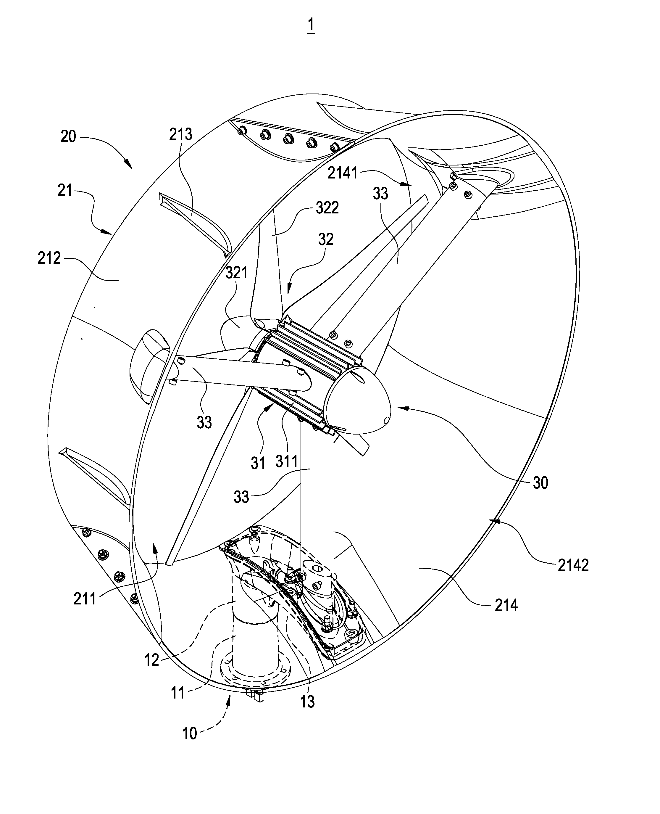
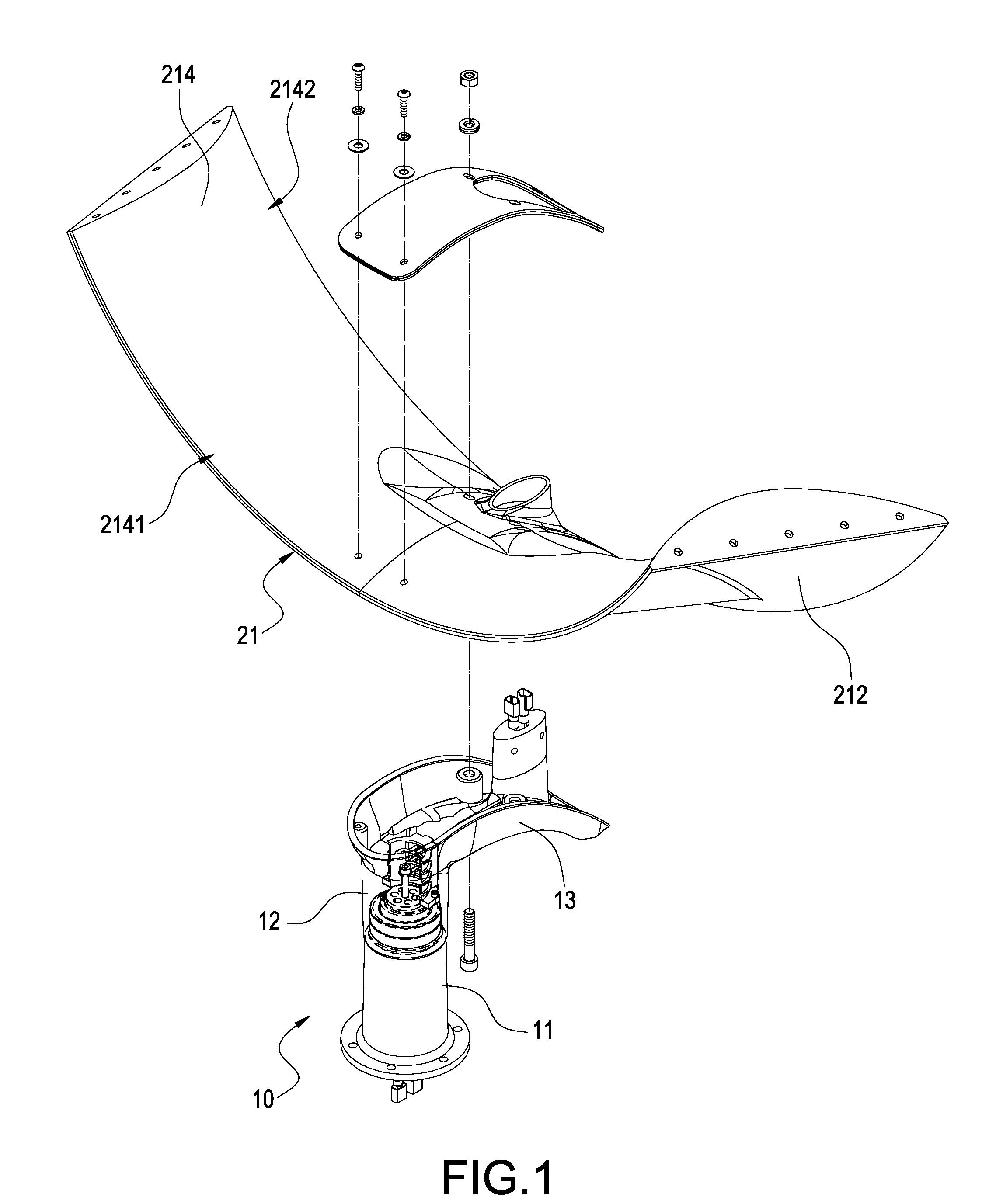
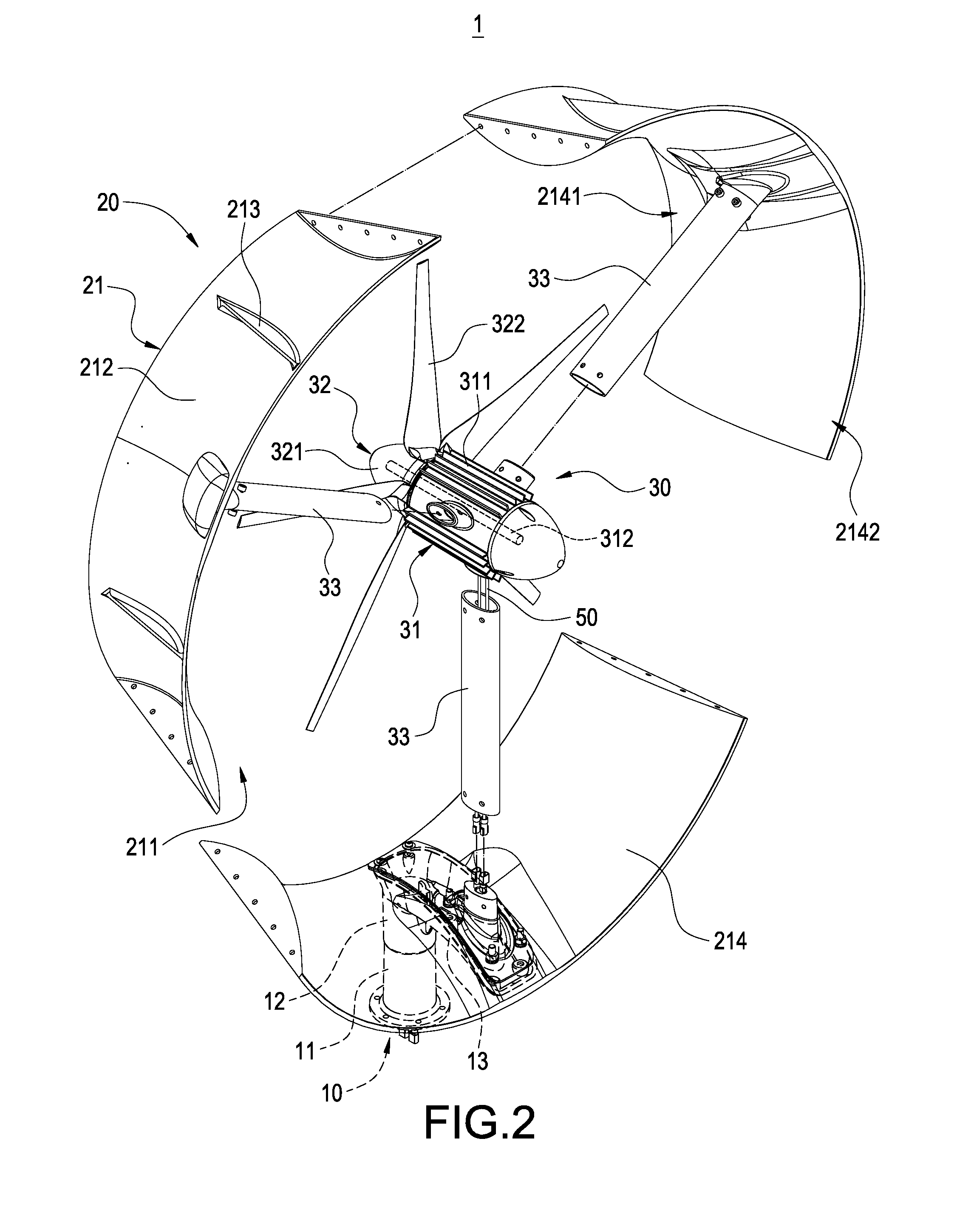
[0022]Please refer to FIGS. 1 to 3. FIG. 1 is an exploded perspective view showing a wind-guiding shroud and a post of the present invention. FIG. 2 is an exploded perspective view of the present invention. FIG. 3 is a perspective view showing the external appearance of the present invention. The present invention provides a wind-power generating device 1 with automatic adjustment to wind direction, which includes a post 10, a wind-guiding shroud 20, a generator assembly 30 and a wind turbine 32.

[0023]The post 10 has a fixed section 11, a rotatable section 12 pivotally connected to an upper portion of the fixed section 11, and a supporting arm 13 connected to th...


PUM


Abstract

A wind-power generating device (1) with automatic adjustment to wind direction includes a post (10), a wind-guiding shroud (20), and a generator assembly (30). The post (10) has a fixed section (11) and a rotatable section (12) pivotally connected to an upper portion of the fixed section (11). The wind-guiding shroud (20) is fixed to the rotatable section (12). The interior of the wind-guiding shroud (20) is formed with an accommodating space (211), and the exterior thereof is formed with an outer curved surface (212) expanding gradually toward its rearward. The generator assembly (30) is fixed in the accommodating space (211). The outer curved surface (212) is blown by the wind, so that the wind-guiding shroud (20) can rotate with automatic adjustment to the wind direction by the rotatable section (12).

Description

BACKGROUND OF THE INVENTION[0001]1. Field of the Invention[0002]The present invention relates to a wind-power generating device, and in particular to a wind-power generating device with automatic adjustment to wind direction.[0003]2. Description of Prior Art[0004]With the rise of the concept of environmental protection, more attention has been paid to the technologies of generating electricity from natural resources. Thus, many countries aim to develop the technologies of generating electricity from the wind power.[0005]Conventionally, a wind-power generating device includes a main body, a wind turbine, a post and a generator. The post is usually fixed on the ground, but it is not limited thereto. The post may be fixed to a roof of a house or a car. The top of the post is connected to the bottom of the main body. The generator is usually received inside the main body and provided with a spindle. The wind turbine is located in front of the main body and pivotally connected to the spi...

Claims


Application Information

Patent Timeline
IPC IPC(8): F03D1/04F03D9/00
CPCF03D1/04F03D7/0208Y02E10/723F05B2240/133F05B2250/5011F05B2240/13Y02E10/728Y02E10/72F03D9/25F03D13/20
Inventor CHEN, SHIH H.
Owner JETPRO TECH
Why Eureka
Try Eureka