RFID tag especially for use near conductive objects

Inactive Publication Date: 2010-12-09
GASNGO R&D LTD
View PDF27 Cites 46 Cited by
  • Summary
  • Abstract
  • Description
  • Claims
  • Application Information

AI Technical Summary

Benefits of technology

[0014]Embodiments of the present invention successfully addresses at least some of the shortcomings of the prior art by providing an antenna assembly for an RFID tag (powered, but especially a passive RFID tag), an RFID tag comprising such an antenna assembly and a method of making such an antenna assembly, the antenna assembly including a loop antenna located at a distance from a shielding layer comprising an electromagnetic s

Problems solved by technology

It is known that it is challenging to use passive RFID tags of the frequencies suitable for short range transmission (generally, less than about 100 MHz, e.g. 13.56 MHz or 125 KHz) in the proximity of conductive materials such as a metal object (such as a vehicle body) due to the generation of eddy currents in the conductive material which generates a magnetic field opposite to the reader magnetic field, significantly attenuating the magnetic flux through the RFID tag antenna coil, reducing the amo

Method used


Image

  • RFID tag especially for use near conductive objects
  • RFID tag especially for use near conductive objects
  • RFID tag especially for use near conductive objects

Examples


Embodiment Construction

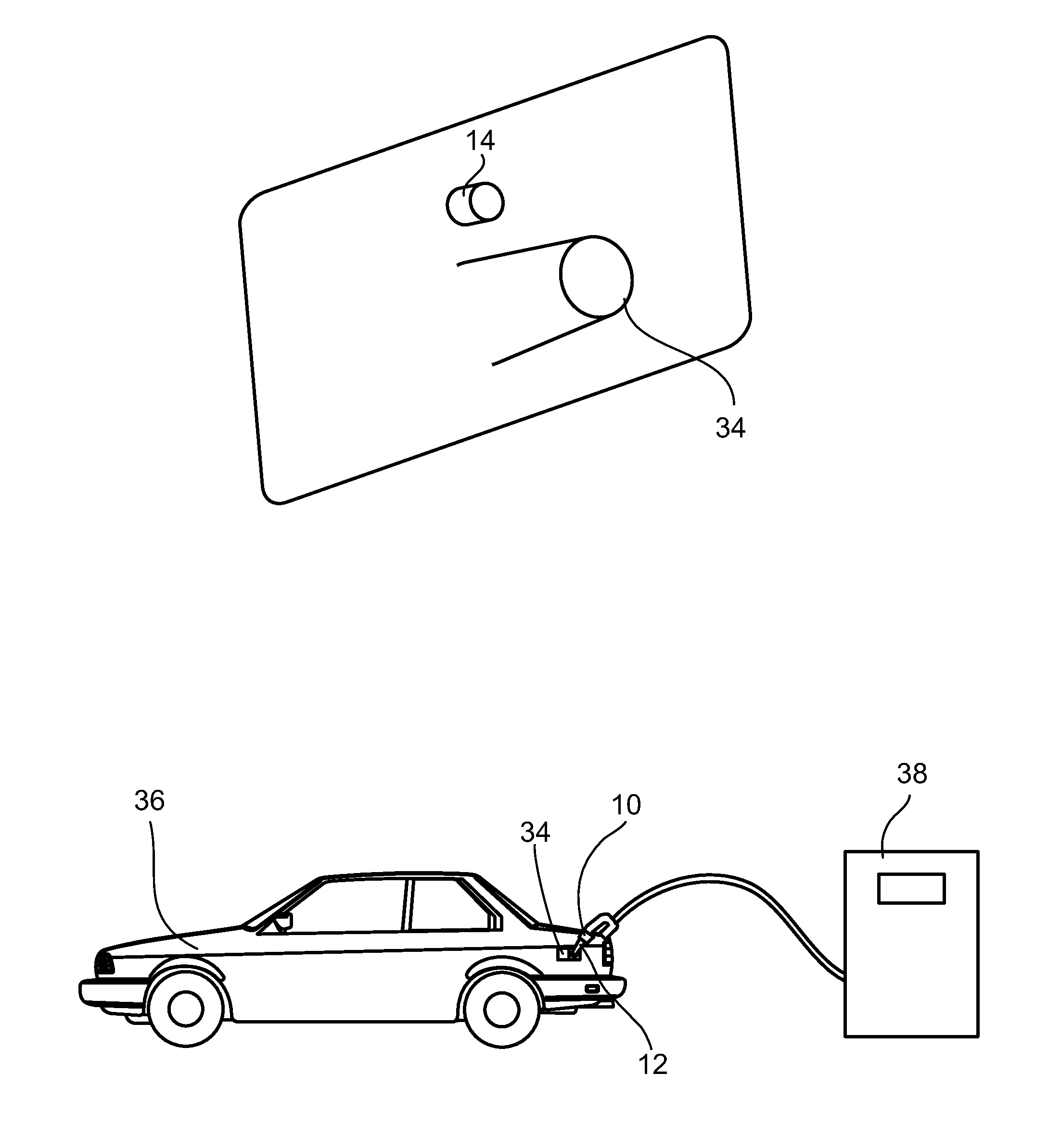
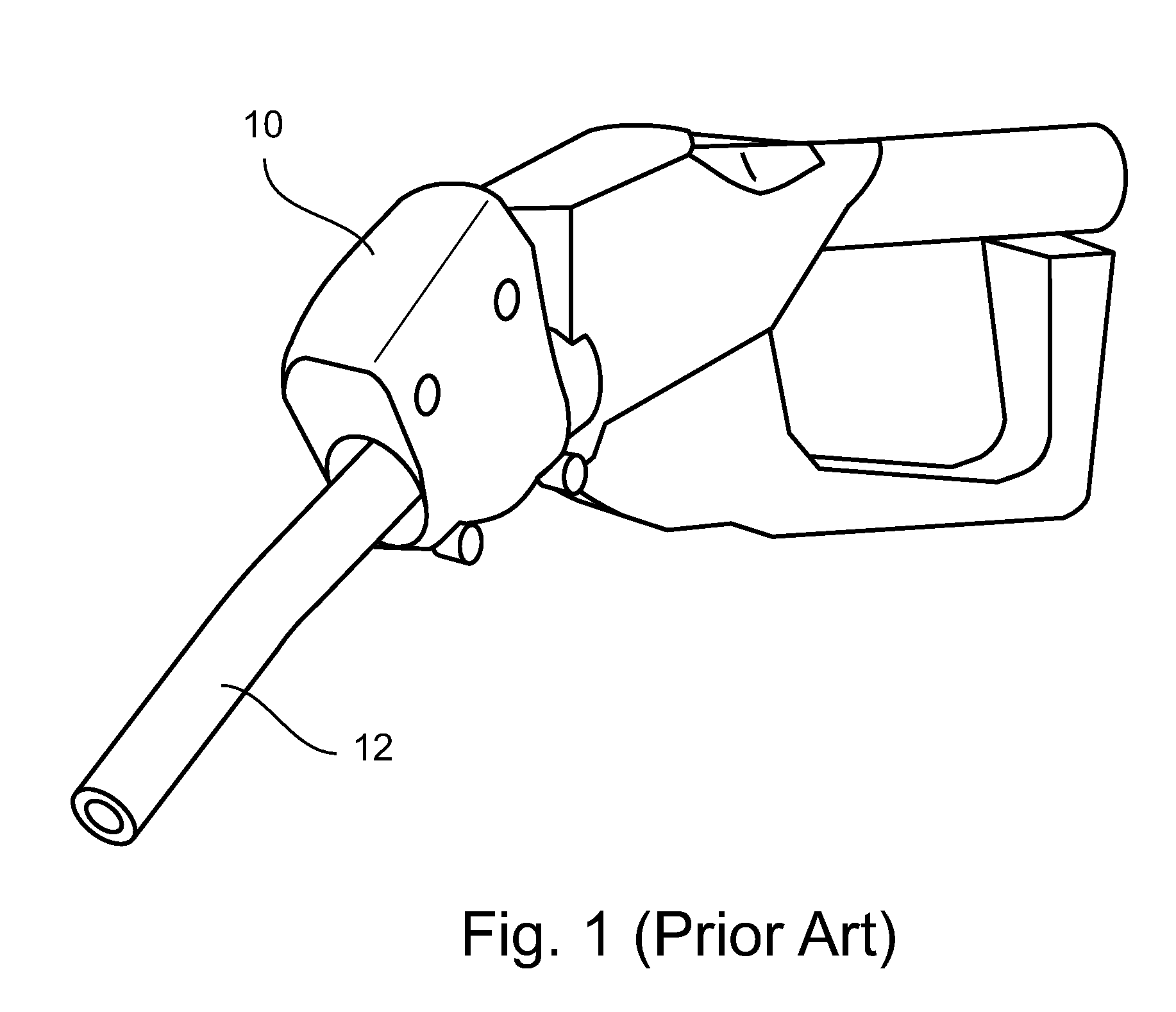
[0067]Embodiments of the present invention relates to antenna assemblies useful for increasing the utility of RFID tags, especially passive RFID tags, in close proximity of a conductive material such as a metal. In a specific implementation, the teachings of the present invention are applied to provide thin passive vehicle identification tags that may be secured in the proximity of a vehicle refueling port and read by a vehicle identification tag reader mounted on a fuel-dispensing nozzle. Embodiments of the present invention allow significant savings by allowing for very cheap identification tags that can be read with relatively little energy expenditure by a vehicle identification tag reader.

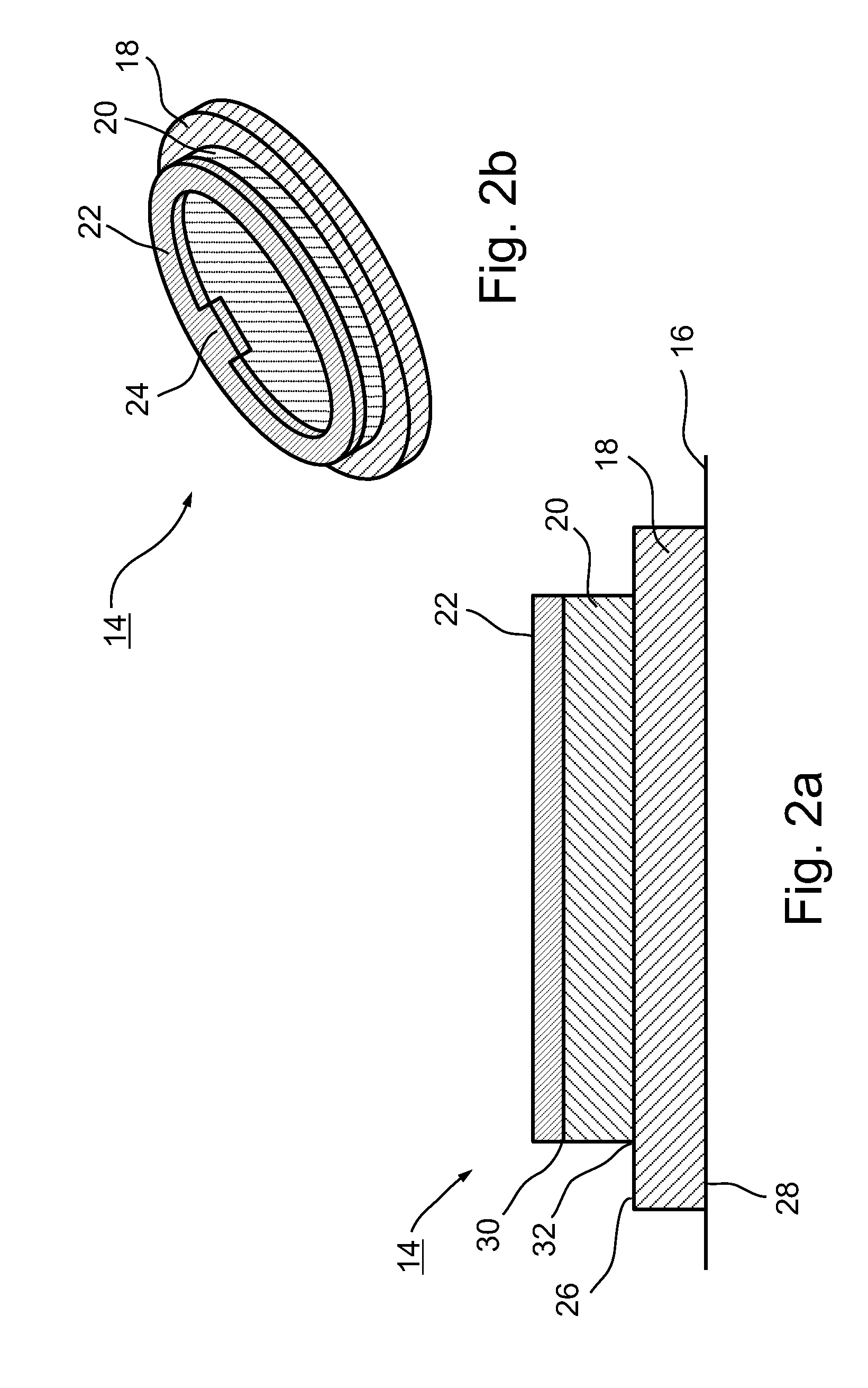
[0068]The principles and operation of an RFID tag of the present invention provided with an antenna assembly of the present invention may be better understood with reference to the drawings and accompanying descriptions.

[0069]Before explaining at least one embodiment of the invention in detail...


PUM


Abstract

An RFID tag comprising an antenna assembly, including a shielding layer comprising an electromagnetic shielding material, a radio frequency loop antenna, and a spacer comprising a spacer material having a permittivity less than about 2 interposed between the antenna and the shielding layer is disclosed. Also disclosed are methods of manufacturing such an RFID tag. Also disclosed is the use of such an RFID tag for use in identifying a vehicle, for example in the context of fuel-purchase authorization.

Description

RELATED APPLICATION[0001]The present application claims the benefit under 119(e) of a US provisional application with same inventors and same title, Ser. No. 60 / 960,901 and filed on Oct. 19, 2007, the disclosure of which is incorporated herein by reference.FIELD AND BACKGROUND OF THE INVENTION[0002]The present invention, in some embodiments thereof, relates to the fields of logistics and radio frequency communications and, more particularly, to RFID tags including an antenna that provide reasonable signal strengths when in the proximity of metal objects such as motor vehicles that is useful, for example, for fuel-purchase authorization.[0003]To be successful, a service station generally dispenses fuel to as many vehicles as possible in a given period of time. This is achieved, for example, by providing high speed entrance and egress and many fuel-dispensing locations (i.e., fuel pumps), arranged for high-throughput refueling of many continuously arriving vehicles.[0004]One preferred...

Claims


Application Information

Patent Timeline
IPC IPC(8): H04Q5/22G06K19/077
CPCB60K15/04G06K19/07771B67D7/348
Inventor WEITZHANDLER, SHIMONVILNAI, YOAVLEVIE, ILAYYALON, AVI
Owner GASNGO R&D LTD
Why Eureka
Try Eureka