
Method and apparatus for forecasting shadowing for a photovoltaic system

a photovoltaic system and shadowing technology, applied in the direction of solar heating energy, random distribution of objects, material dimension control, etc., can solve the problem that the minimum power cannot always be generated

Inactive Publication Date: 2010-12-09
ADENSIS
View PDF39 Cites 106 Cited by
  • Summary
  • Abstract
  • Description
  • Claims
  • Application Information

AI Technical Summary

Benefits of technology

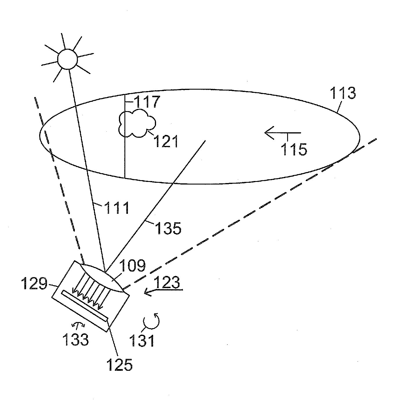
[0020]The second embodiment is based on the concept that, if the wind direction is known, one can look from the reference point to a location adjacent to the sun to recognize cloud movements that take place towards the reference point and will cause shadowing at a later time. Starting with this basic approach, according to an alternative to the previous embodiment, a line from the PV system or its immediate surroundings to the actual position of the sun is determined, the predetermined region is formed around this line, and passage of the clouds through this region is measured. In this way, the region quasi migrates with the position of the sun, and the region between the PV system and the sun is always observed. To analyze cloud movement, a horizontal reference line is placed in the region, and the passage or crossing of the clouds relative to the reference line is evaluated. A second reference line placed parallel to the first reference line enables determination of the velocity of the cloud movement.

Problems solved by technology

Depending on the weather, this minimum power cannot always be generated by the solar system alone.

Method used


Image

  • Method and apparatus for forecasting shadowing for a photovoltaic system
  • Method and apparatus for forecasting shadowing for a photovoltaic system
  • Method and apparatus for forecasting shadowing for a photovoltaic system

Examples


Embodiment Construction

[0038]Throughout all the figures, same or corresponding elements may generally be indicated by same reference numerals. These depicted embodiments are to be understood as illustrative of the invention and not as limiting in any way. It should also be understood that the figures are not necessarily to scale and that the embodiments are sometimes illustrated by graphic symbols, phantom lines, diagrammatic representations and fragmentary views. In certain instances, details which are not necessary for an understanding of the present invention or which render other details difficult to perceive may have been omitted.

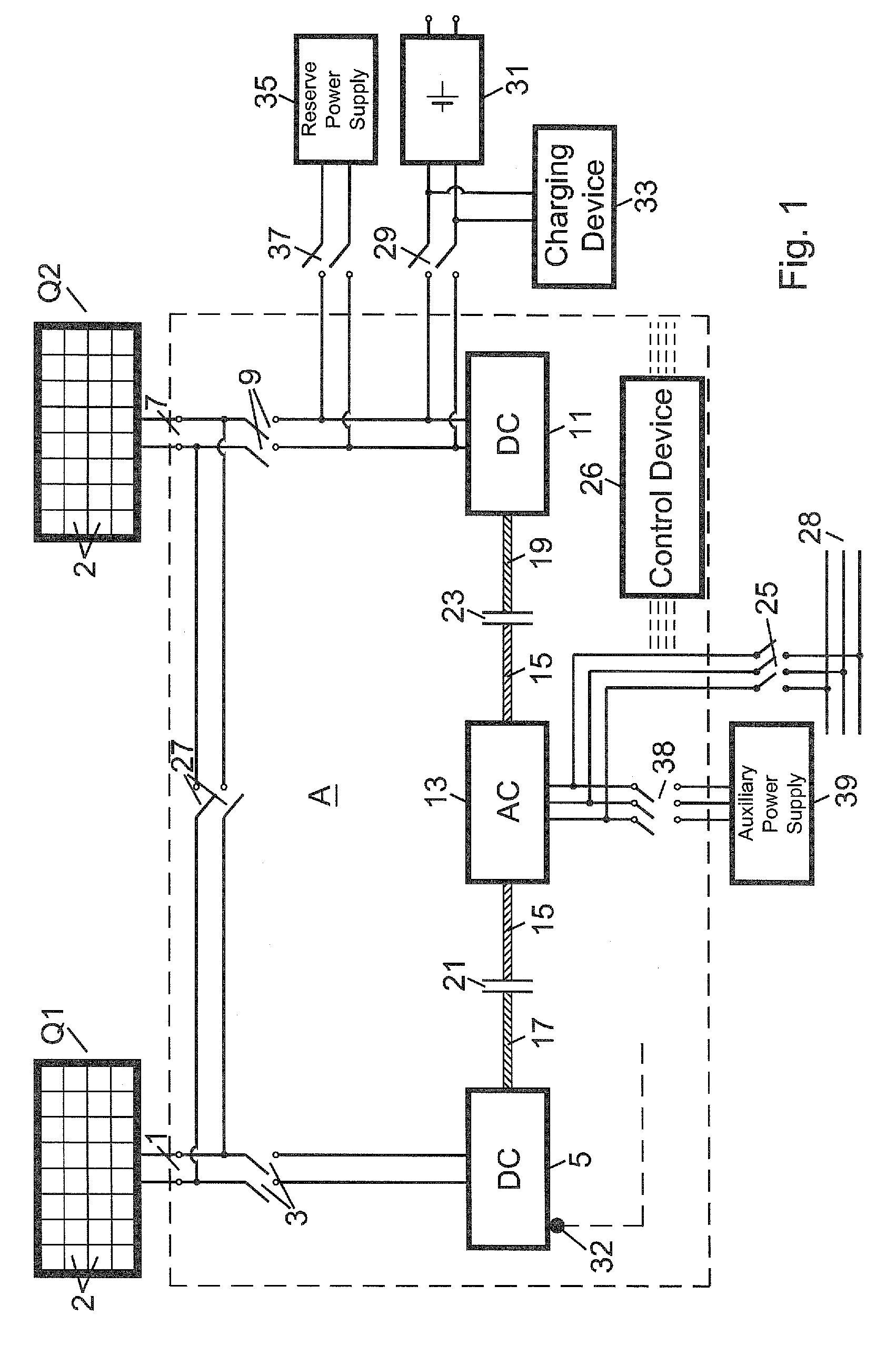
[0039]Turning now to the drawing, and in particular to FIG. 1, there is shown a photovoltaic system A with a first subset of photovoltaic modules Q1 (not individually shown in FIG. 1) as a first energy source, which has an output first terminal pair 1 configured for supplying a DC voltage and a DC current. The output terminal pair 1 can be connected to a first externally-exc...


PUM


Abstract

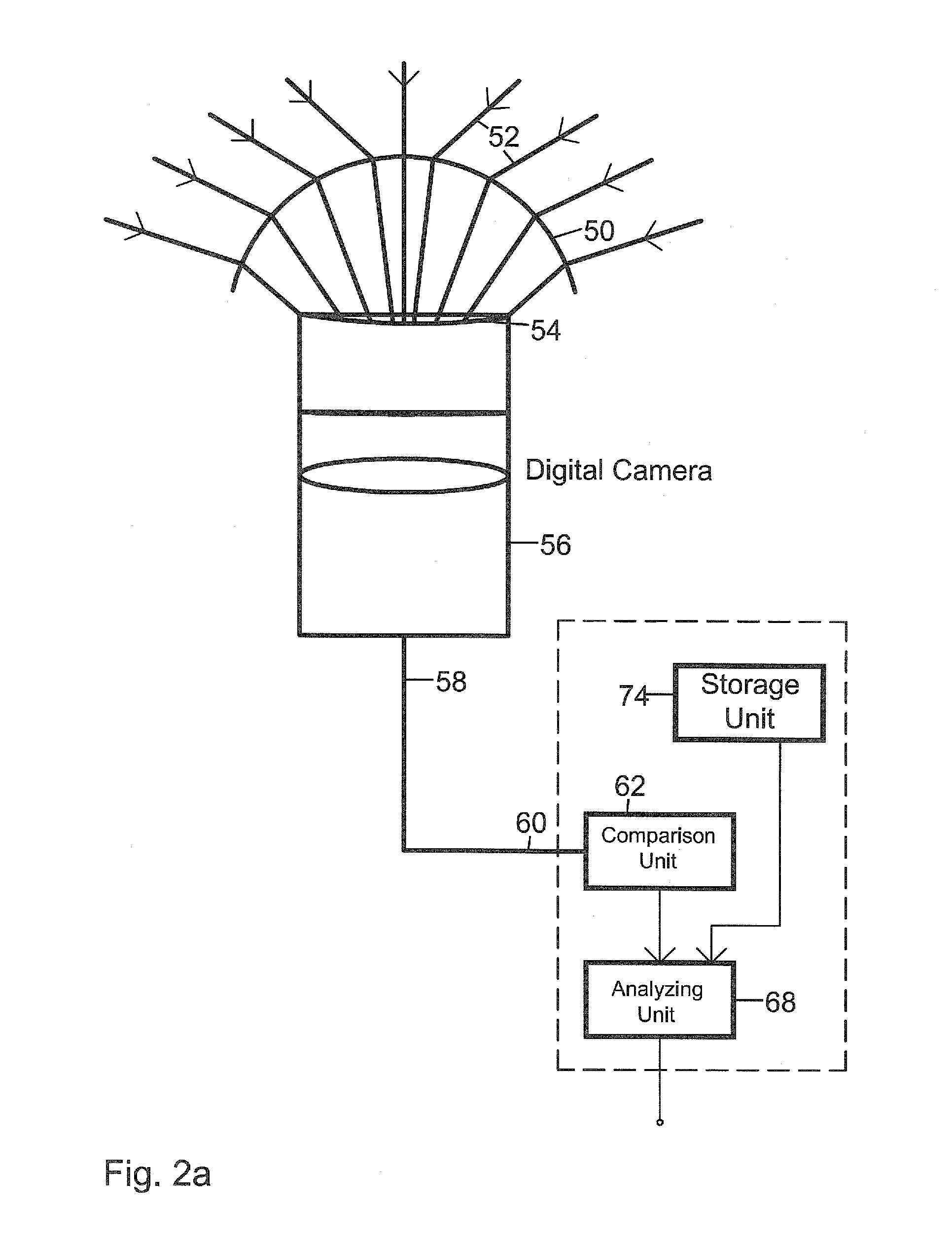
In a method for forecasting shadowing of a photovoltaic (PV) system due to cloud formation or movement, part of the firmament is imaged with fisheye optics onto the input optics of a digital camera. Pixel groups associated with luminous intensity ranges are formed. The spatial arrangement of the groups is analyzed to forecast shadowing of a photovoltaic system. A line extending from the PV system to the sun is formed and is continuously tracked. A reference line located inside a region around the line is formed. Passage of clouds across a reference line is analyzed. The result of the analysis is used to increase the electric power from the PV system to a minimum value through supply of additional backup energy or to reduce the electric power consumption by disconnecting users to ensure that key users do not experience a drop in supplied power below a minimum value.

Description

CROSS-REFERENCES TO RELATED APPLICATIONS[0001]This application claims the priority of German Patent Application, Serial No. 10 2009 024 212.0, filed Jun. 8, 2009, pursuant to 35 U.S.C. 119(a)-(d), the content of which is incorporated herein by reference in its entirety as if fully set forth herein.BACKGROUND OF THE INVENTION[0002]The present invention relates to a method and an apparatus for forecasting forthcoming shadowing of a photovoltaic system connected to a power grid due to cloud formation or cloud movement.[0003]The following discussion of related art is provided to assist the reader in understanding the advantages of the invention, and is not to be construed as an admission that this related art is prior art to this invention.[0004]Supply contracts with associated energy providers frequently require that the solar power plants are designed to supply to the power grid an agreed-upon minimum power within a determined time interval. For example, a 2.4 MW solar power plant may...

Claims


Application Information

Patent Timeline
Patent Type & Authority Applications(United States)
IPC IPC(8): H04N5/225G06K9/00
CPCG01W1/10F24J2/40H01L31/02021G01W1/12F24S50/00F24S2020/16F24S2201/00Y02A90/10
Inventor BECK, BERNHARD
Owner ADENSIS
Learn More