
Loudspeaker having an interlocking magnet structure

a technology of interlocking magnets and loudspeakers, which is applied in the field of loudspeakers, can solve the problems of affecting the adhesive used in the magnet structure, the oscillation of the voice coil, and the movement of the diaphragm, and achieves the effects of stable mechanical connections, reduced manufacturing costs, and reduced manufacturing costs

Active Publication Date: 2010-12-09
HARMAN INT IND INC +1
View PDF33 Cites 7 Cited by
  • Summary
  • Abstract
  • Description
  • Claims
  • Application Information

AI Technical Summary

Benefits of technology

The patent describes a magnet structure for use with a loudspeaker that includes a magnet, a core cap, and a shell pot. The magnet may have an aperture and the shell pot may have a protrusion that interlock with each other to securely position the magnet. The core cap may have extensions that enter the aperture and engage with the magnet. The magnet may also have a recess in the shell pot or no aperture and interlock with the shell pot using a flange. The magnet structure may also have a venting passageway for heat and acoustical tuning. The manufacturing process may be simple and cost-effective. The technical effects of the patent include stable mechanical connections, improved heat and acoustical tuning, and reduced manufacturing expenses.

Problems solved by technology

This causes the voice coil to oscillate, which in turn causes the diaphragm to move.
Adhesive used in the magnet structure may be affected by working environment of loudspeakers such as temperature fluctuations, including hot or cold weather, wet conditions, etc.

Method used


Image

  • Loudspeaker having an interlocking magnet structure
  • Loudspeaker having an interlocking magnet structure
  • Loudspeaker having an interlocking magnet structure

Examples


Embodiment Construction

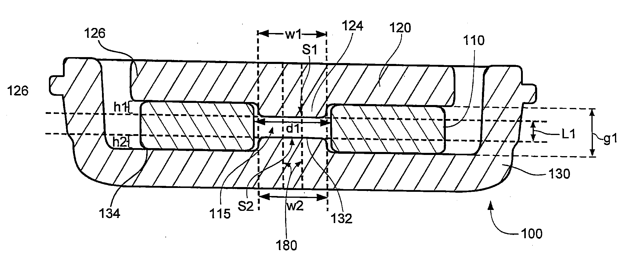
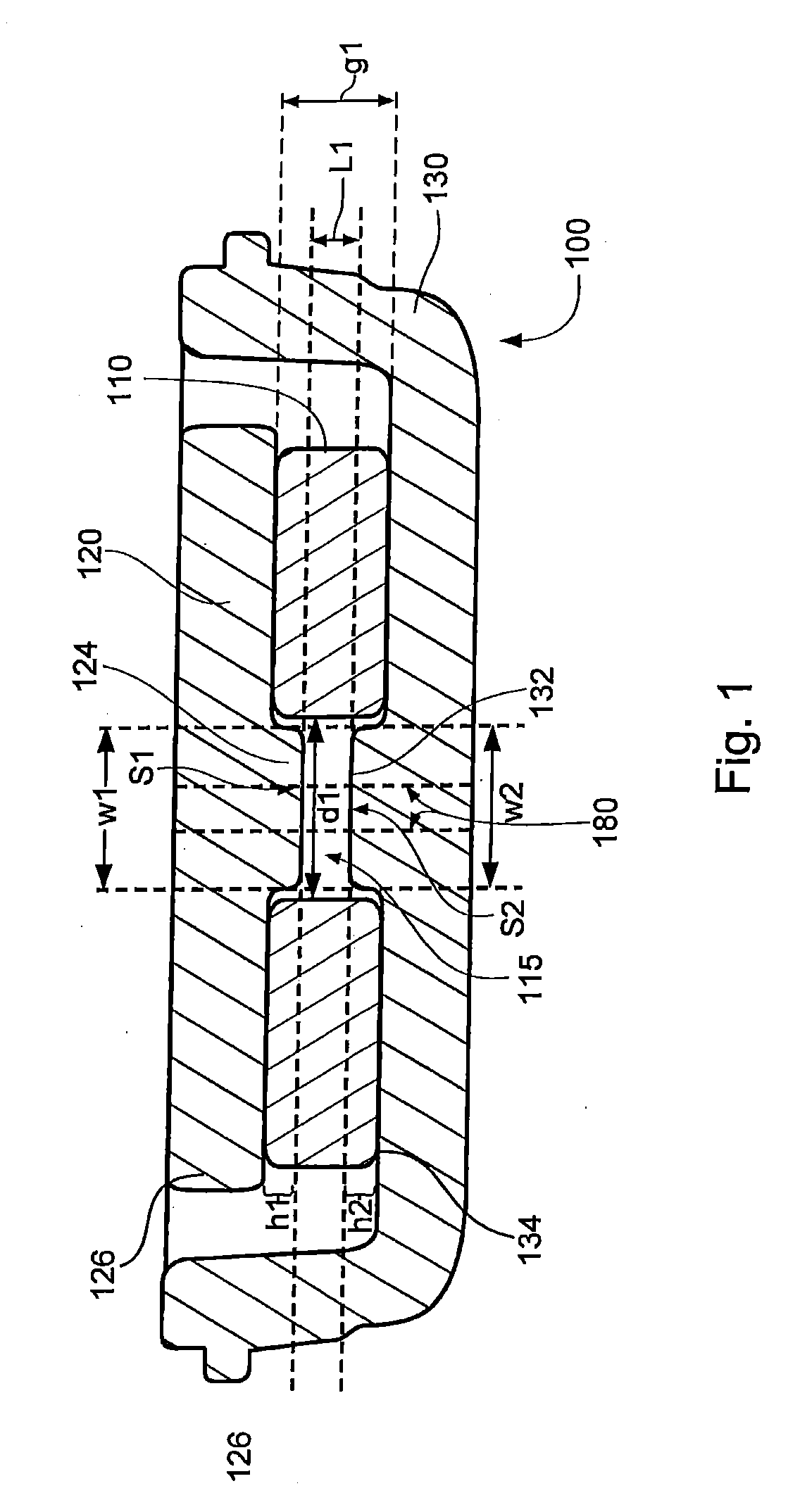
[0028]FIG. 1 illustrates a first example of an interlocking magnet structure 100 for a single magnet type. The interlocking magnet structure 100 may include a magnet 110, a core cap 120 and a shell pot 130 that are configured to interlock with one another. The magnet 110 may be made from various materials such as neodymium, ceramic, etc. The core cap 120 and the shell pot 130 may be made from ferromagnetic materials, such as iron, steel, etc. but are not limited thereto. In FIG. 1, the magnet 110 has disc shape; in other examples, the magnet 110 may have other shapes such as a rectangular shape. The magnet 110 may be formed to define an aperture 115 in its center. The aperture 115 has a diameter d1 and a depth g1. Length L1 may be a distance between a surface 51 of the core cap 120 and a surface S2 of the shell pot 130. The length L1 may be provided to avoid a magnetic short circuit.

[0029]The core cap 120 may have a disc shape and be placed on the disc-shaped magnet 110, as shown in...


PUM


Abstract

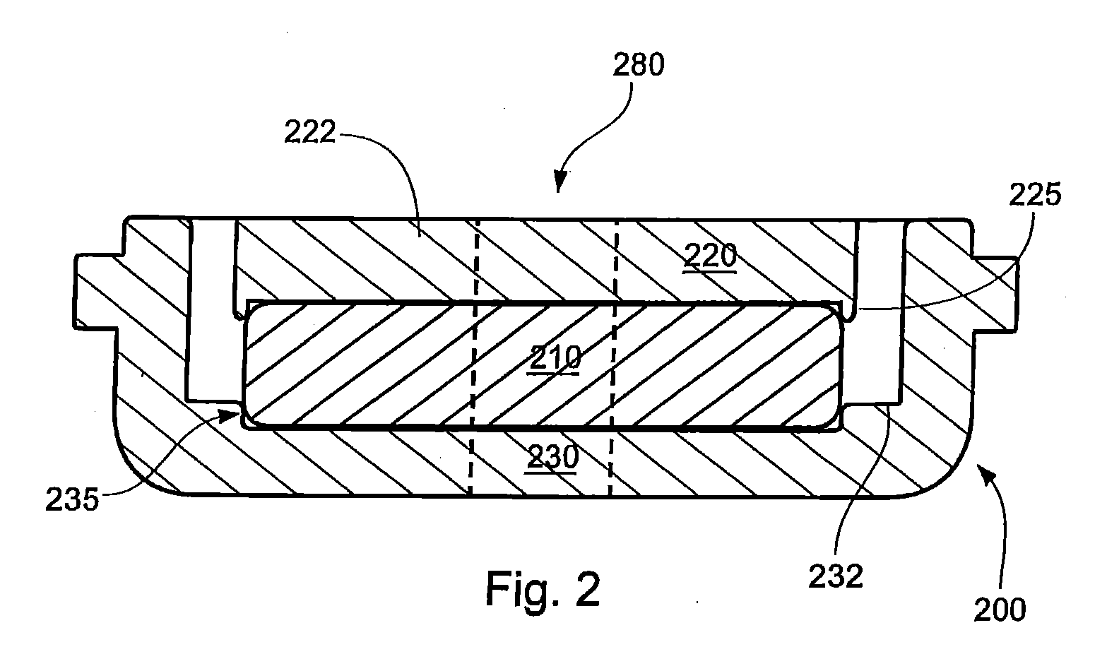
A magnet structure for use with a loudspeaker has an interlocking mechanism. The magnet structure can include a magnet, a shell pot and at least one core cap. The shell pot can contain the magnet in its hollow interior. The magnet can be a single magnet or double magnets. The core cap has two surfaces. For a single magnet, one surface of the core cap faces the magnet. For double magnets, the core cap can be vertically disposed between the two magnets. The magnet, the core cap and the shell pot can interlock with one another such that a position of the magnet relative to the core cap and the shell pot can be rigidly preserved. The magnet can be configured to be, for example, overlapped, inserted, staked and / or engaged with at least one of the shell pot or the core cap.

Description

PRIORITY CLAIM[0001]This application is a continuation of U.S. patent application Ser. No. 11 / 386,359 entitled LOUDSPEAKER HAVING AN INTERLOCKING MAGNET STRUCTURE, filed on Mar. 22, 2006, which is incorporated by reference in its entirety.BACKGROUND OF THE INVENTION[0002]1. Technical Field[0003]This invention relates to a loudspeaker and more particularly, to a loudspeaker having an interlocking magnet structure.[0004]2. Related Art[0005]A transducer is a device that converts one form of an input signal to another form. Loudspeakers are one example of a transducer. Loudspeakers convert electrical signals to sound. Loudspeakers include a diaphragm, a voice coil and a magnet. The voice coil is connected to the diaphragm and disposed in an air gap. The magnet generates magnetic flux in the air gap. As input current flows through the voice coil, it creates an induced magnetic field that reacts with the magnetic flux in the air gap generated by the magnet. This causes the voice coil to o...

Claims


Application Information

Patent Timeline
Patent Type & Authority Applications(United States)
IPC IPC(8): H04R11/02
CPCH04R9/025
Inventor MIHELICH, RYAN J.SEMMLER, JASON M.STEERE, JOHN F.
Owner HARMAN INT IND INC
Learn More