
Device for connecting two segments of a propelling nozzle

a technology for propelling nozzles and devices, which is applied in the field of rocket engine nozzles and assembling propulsion nozzles, can solve the problems of large thermal and mechanical stresses on the physical connection between the segments, and the typical thermal stress on the propulsion nozzles of rocket engines

Inactive Publication Date: 2016-06-16
ARIANEGRP SAS
View PDF8 Cites 7 Cited by
  • Summary
  • Abstract
  • Description
  • Claims
  • Application Information

AI Technical Summary

Benefits of technology

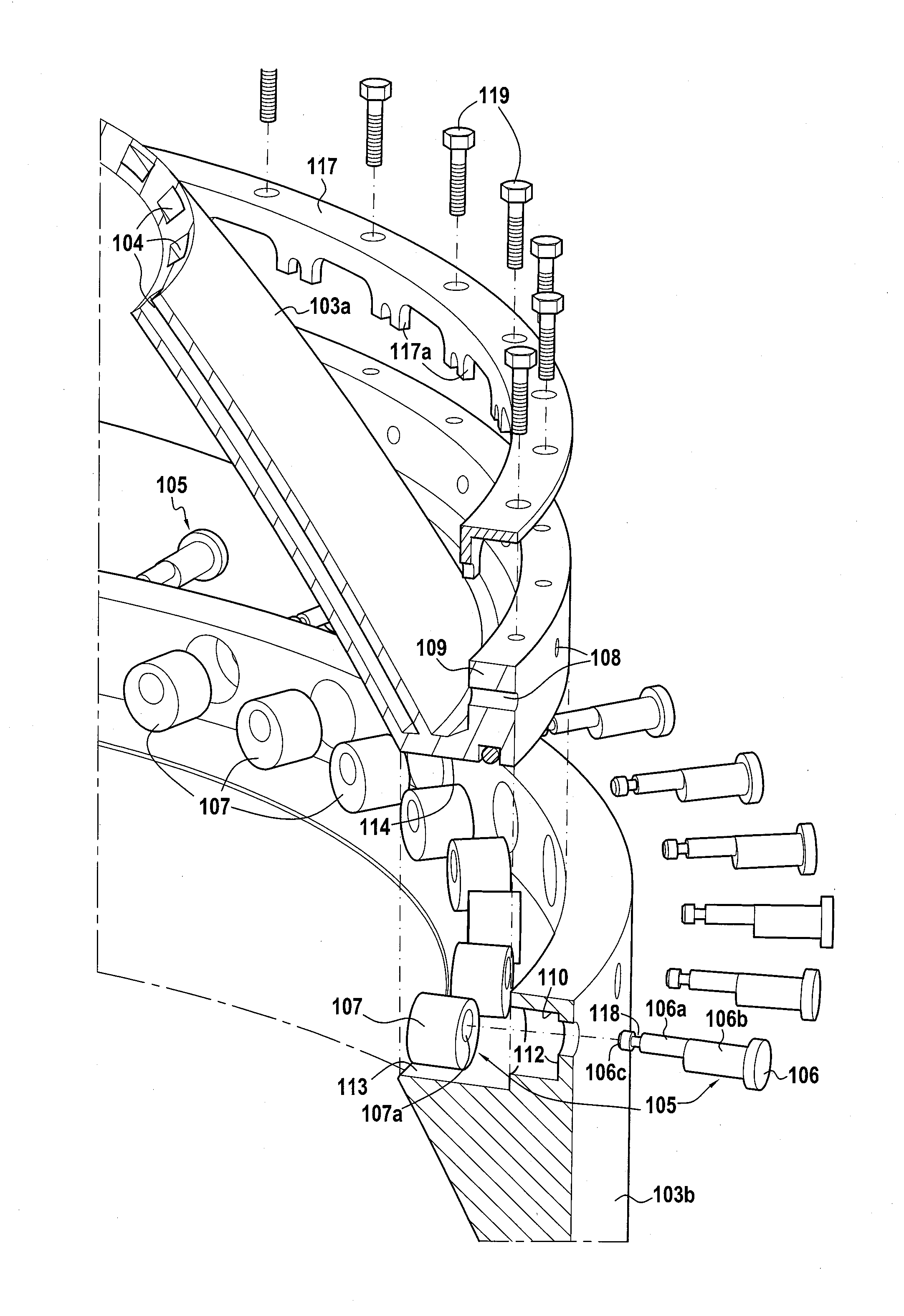
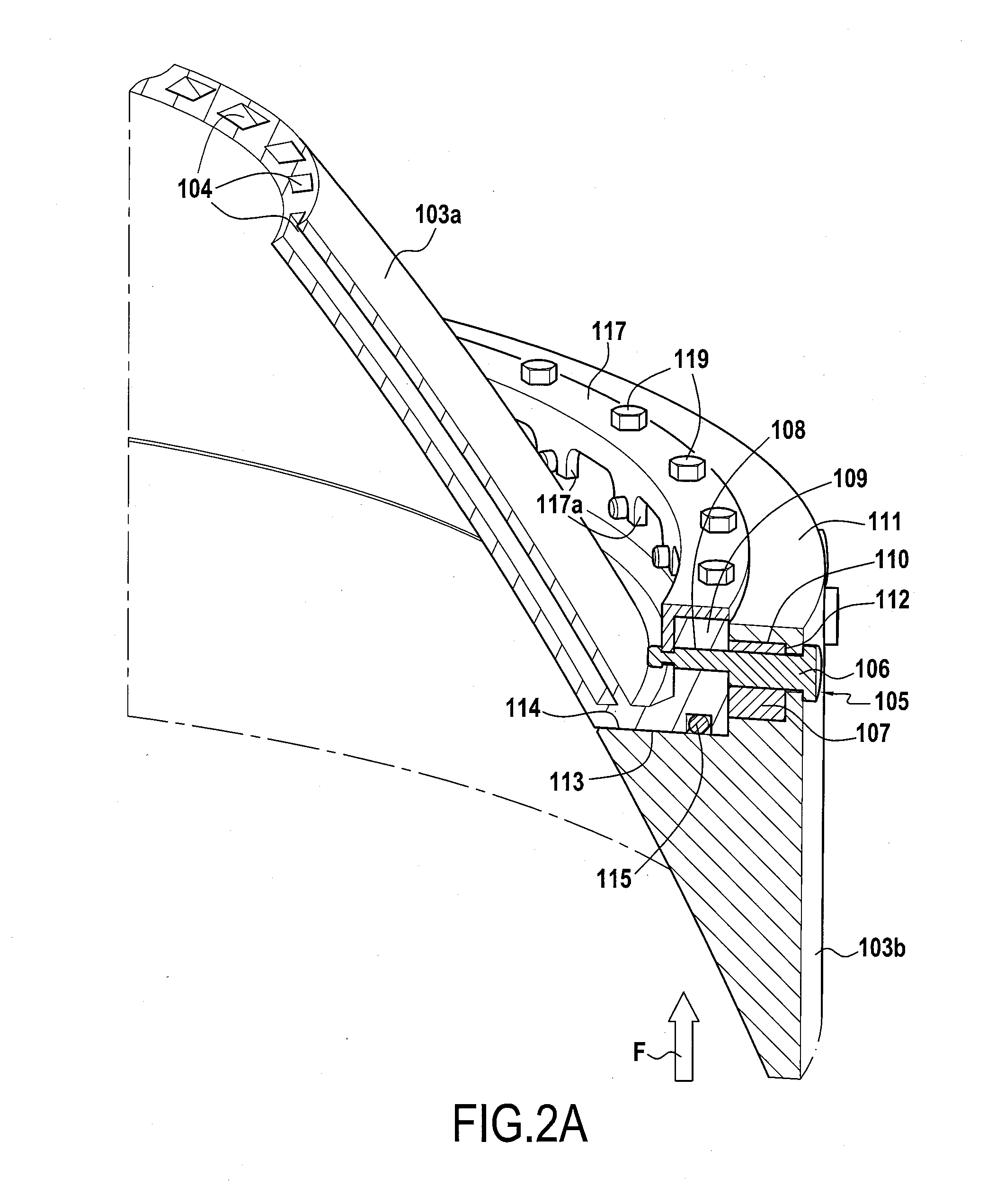
The present disclosure proposes a device for connecting together two segments of a propulsion nozzle that are made of thermally dissimilar materials by using a pin and an eccentric bushing. The device provides a reliable mechanical connection between the segments even under high thermal stresses. The eccentricity of the surfaces of the pin and bushing allows for adjustment of the position of the pin's axis in relation to the bushing's axis to connect the segments even if their radial orifices are not perfectly aligned. The device allows for an axial prestress to be maintained between the segments to ensure a constant mechanical connection between them. The connection device can be adapted to different relative positions of the segments' radial orifices in the axial direction of the nozzle to maintain prestress in that direction.

Problems solved by technology

Consequently, the propulsion nozzles of rocket engines are typically subjected to extreme thermal stresses, since they come directly into contact with such combustion gas.
The different thermal characteristics of such materials can nevertheless raise major drawbacks.
In particular, the physical connection between the segments may be subjected to large thermal and mechanical stresses as a result of the dissimilar thermal properties of the materials of the two segments.
Thus, the different coefficients of thermal expansion may lead to major mechanical stresses on the connection between the two segments.
Also, the difference between the thermal conductivities of the two materials can also give rise to large temperature differences in the proximity of the junction between the two segments.

Method used


Image

  • Device for connecting two segments of a propelling nozzle
  • Device for connecting two segments of a propelling nozzle
  • Device for connecting two segments of a propelling nozzle

Examples


Embodiment Construction

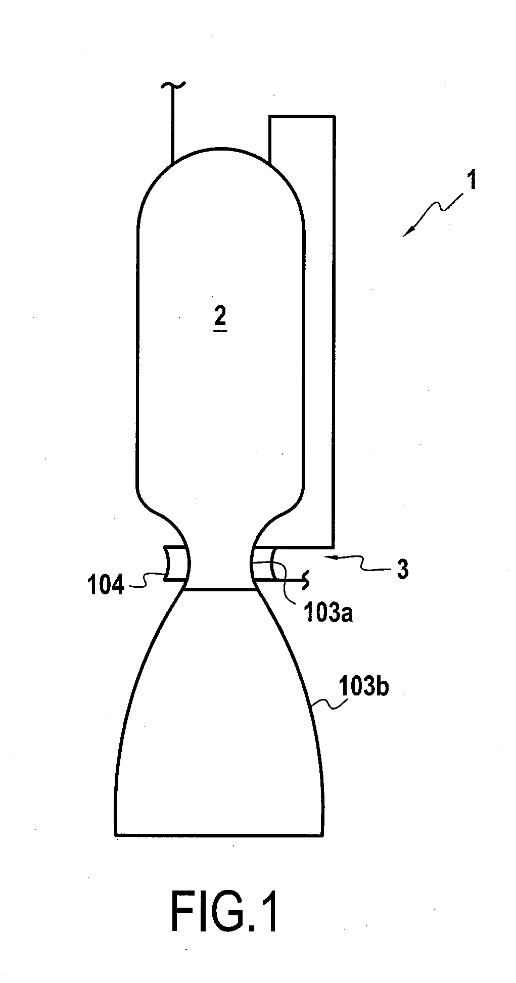
[0031]FIG. 1 shows a rocket engine 1 in part, and more specifically an assembly comprising a propulsion chamber formed by a combustion chamber 2 extended by a convergent-divergent nozzle 3. In order to lighten this assembly, the convergent-divergent nozzle 3 is made up of two segments 103a, 103b: a throat 103a and a divergent portion 103b. The throat 103a is formed integrally with the combustion chamber 2 that is made of high-temperature resistant metal material, and in the example shown, it presents regenerative cooling ducts 104 for exchanging heat with a propellant of the rocket engine 1. In contrast, the divergent portion 103b is made of composite material, e.g. a carbon / carbon (C / C) ceramic matrix composite, of the carbon silicon carbide (C-SiC), or of the silicon carbide silicon carbide (SiC-SiC) type, using fibers of carbon or of silicon carbide.

[0032]Because of the greater thermal conductivity of the metal material of the throat 103a, and because it is subjected to regenerat...


PUM

PropertyMeasurementUnit
Symmetryaaaaaaaaaa

Abstract

The invention relates to the field of propulsion nozzles, and in particular to a device (105) for connecting together first and second segments (103a, 103b) of a propulsion nozzle that are made of thermally dissimilar materials. The device (105) comprises at least one pin (106) and an eccentric bushing (107). The pin (106) presents both a first axisymmetric surface (106a) that is to be housed in a radial orifice (108) of the first nozzle segment (103a) and also a second axisymmetric surface (106b) that is eccentric relative to said first axisymmetric surface (106a).

Description

BACKGROUND OF THE INVENTION[0001]The present invention relates to the field of propulsion nozzles, and in particular the field of rocket engine nozzles. More specifically, the present invention relates to assembling a propulsion nozzle comprising first and second segments, said first and second segments being made of materials that are thermally dissimilar.[0002]The term “propulsion nozzle” is used to mean a nozzle of a shape that is appropriate for producing thrust by accelerating a propulsive fluid in a direction opposite from the thrust direction. In the description below, the terms “upstream” and “downstream” are defined relative to the normal flow direction of the propulsive fluid through the nozzle, and the terms “inside” and “outside” indicate respectively the regions inside and outside the nozzle.[0003]Propulsion nozzles may in particular be convergents, for fluids that are not compressible or that reach only subsonic speeds, or they may be convergent-divergent for propulsiv...

Claims


Application Information

Patent Timeline
IPC IPC(8): F02K1/40B23P15/00
CPCF02K1/40B23P15/008F05D2250/73F02K9/343F02K9/97F05D2230/642F05D2260/941F05D2300/50212F05D2260/31
Inventor INDERSIE, DOMINIQUEGUICHARD, DIDIER
Owner ARIANEGRP SAS
Learn More