Compliant material

a technology of compliant materials and joints, applied in the direction of non-disconnectible pipe joints, pipe joints, lighting and heating apparatus, etc., can solve the problems of inability to mechanically reliable connection, reduce the service life of the connection, so as to improve the leaktightness of the connection, the effect of increasing the thermal expansion coefficient and improving the cohesion of the joined members

Active Publication Date: 2012-01-05
SAINT GOBAIN CENT DE RES & DEVS & DETUD EUROEN
View PDF1 Cites 5 Cited by
  • Summary
  • Abstract
  • Description
  • Claims
  • Application Information

AI Technical Summary

Benefits of technology

[0214]The inventors have thus looked for additional solutions in order to improve the leaktightness of the connection between two parts subjected to such stresses and in particular between two parts exhibiting very different thermal expansion coefficients.
[0215]According to an eleventh aspect of the invention, they have thus discovered a device comprising a first member joined to a second member preferably exhibiting a g

Problems solved by technology

The production of ethylene results in a deposition of coke on the internal surfaces of the tubes 12, bringing about a fall in productivity.
In the applications targeted, the connections tested result in losses in leaktightness, indeed even in separation of the tubes.
However, this functional clearance results, at the startup of the pro

Method used


Image

  • Compliant material
  • Compliant material
  • Compliant material

Examples


Embodiment Construction

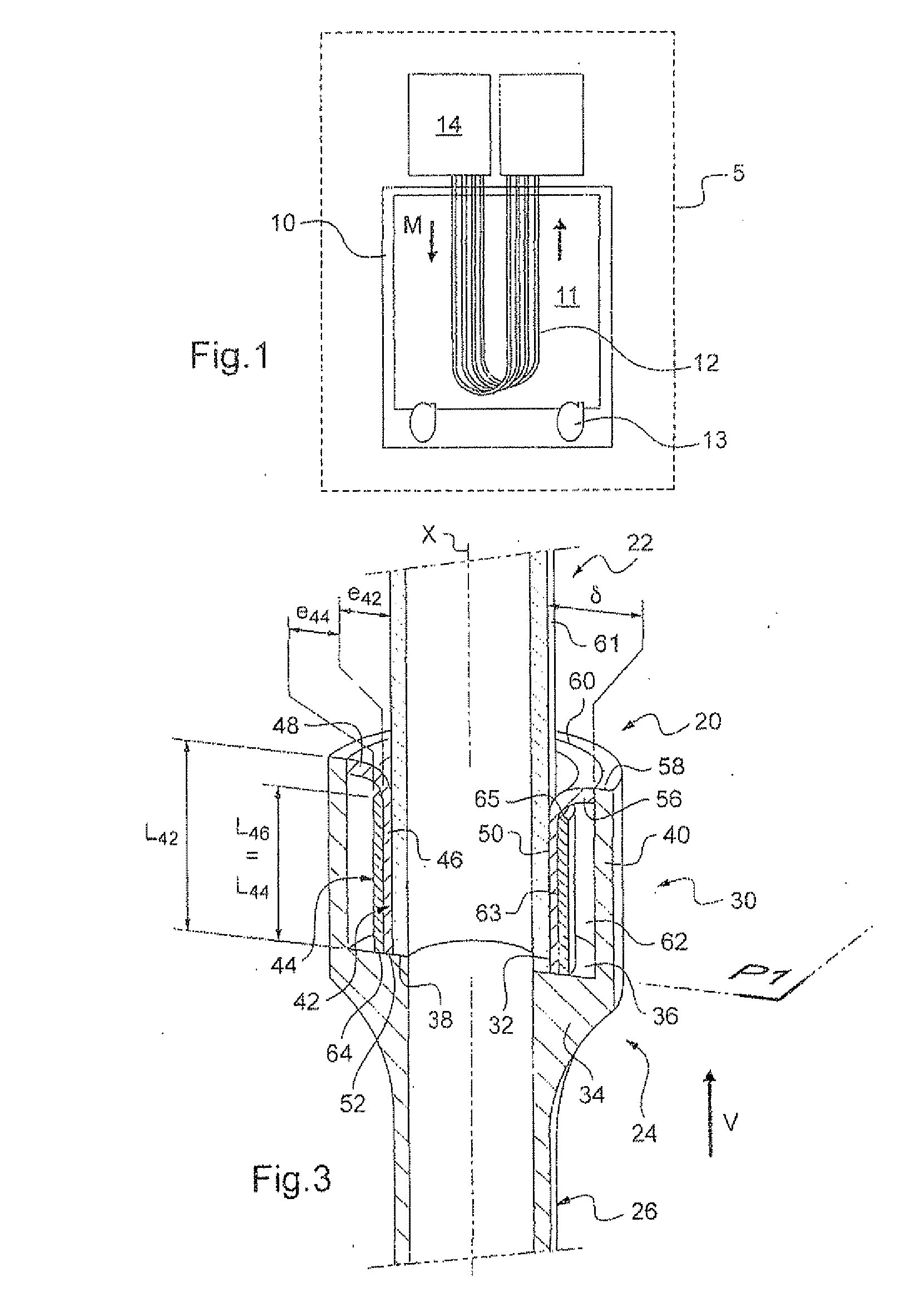
[0264]FIG. 1 was described in the preamble of the description.

[0265]Shrink fitting is a technique for the axial fitting of an external part to an internal part which makes use of the difference in dilatometric behavior between these two parts. The external part is conventionally referred to as “shrink ring”. The internal part is referred to as “shrink fitted”.

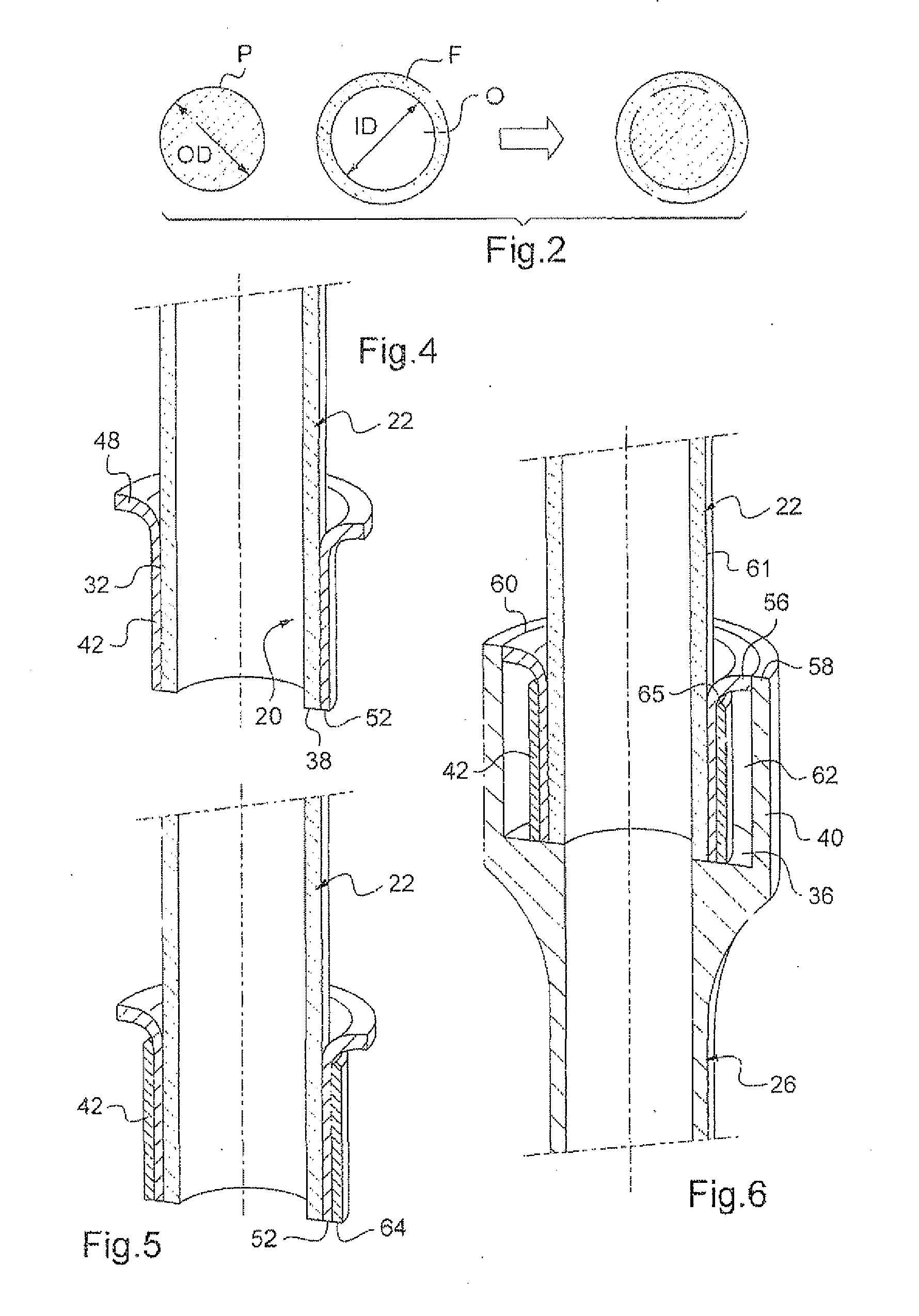
[0266]More specifically, the shrink ring is made of a material exhibiting a greater thermal expansion coefficient than that of the internal part. As represented in FIG. 2, the shrink ring F exhibits an orifice O, delimited by an internal surface, the dimensions of which make it difficult, indeed even impossible, to fit it to the internal part P by hand or even, conventionally, using a press. When the shrink ring F is cylindrical with a circular transverse cross section, its internal diameter ID is thus less than the external diameter OD of the internal part P in the range of temperatures anticipated for the use of the joined co...


PUM

PropertyMeasurementUnit
Temperatureaaaaaaaaaa
Fractionaaaaaaaaaa

Abstract

A device including a first member joined to a second member, the joining being carried out via a compliant material having an alloy with at least two materials selected from silver, gold, and palladium, the second member being a shrink ring of the first member.

Description

TECHNICAL FIELD[0001]The invention relates in particular to an item of equipment chosen from a furnace, a boiler, a superheater, a steam generator, a chemical reactor and a heat exchanger, intended in particular for the production of ethylene. In particular, it relates to means for providing or improving an end-to-end connection between a tube made of ceramic (in particular of silicon carbide) and a metal tube, with or without direct contact between the two tubes.STATE OF THE ART[0002]The production of ethylene results conventionally from a steam cracking operation starting from ethane or naphtha. To this end, an ethylene production unit 5, as represented diagrammatically in FIG. 1, conventionally comprises a furnace 10 comprising a chamber 11 through which passes a bundle of tubes 12 and which is heated by at least one burner 13.[0003]The tubes 12, of circular cross section, exhibit an external diameter of between 50 and 250 mm and a wall with a thickness of between 5 and 25 mm. Th...

Claims


Application Information

Patent Timeline
IPC IPC(8): F16L49/00F16L21/00
CPCC10G9/16C04B2237/84F16L13/004F16L49/00F28F9/185F28F21/04C04B37/026C04B2235/77C04B2235/9607C04B2237/06C04B2237/062C04B2237/064C04B2237/066C04B2237/068C04B2237/122C04B2237/123C04B2237/125C04B2237/126C04B2237/127C04B2237/341C04B2237/343C04B2237/346C04B2237/348C04B2237/365C04B2237/368C04B2237/403C04B2237/405C04B2237/406C04B2237/592C04B2237/708C04B2237/72C04B2237/765C04B2237/82C10G9/203
Inventor HIS, CHRISTIANVILLERMAUX, FRANCELINE
Owner SAINT GOBAIN CENT DE RES & DEVS & DETUD EUROEN
Why Eureka
Try Eureka