

Switching between multiple coupling modes
- Summary
- Abstract
- Description
- Claims
- Application Information
AI Technical Summary
Benefits of technology
Problems solved by technology
Method used
Image

Examples
Embodiment Construction
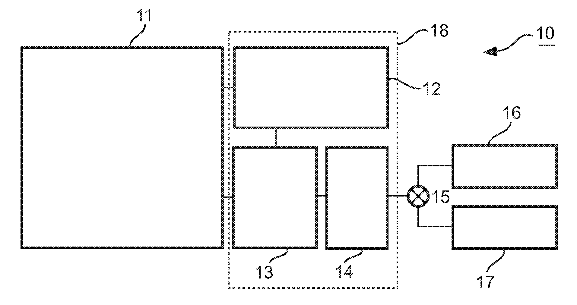
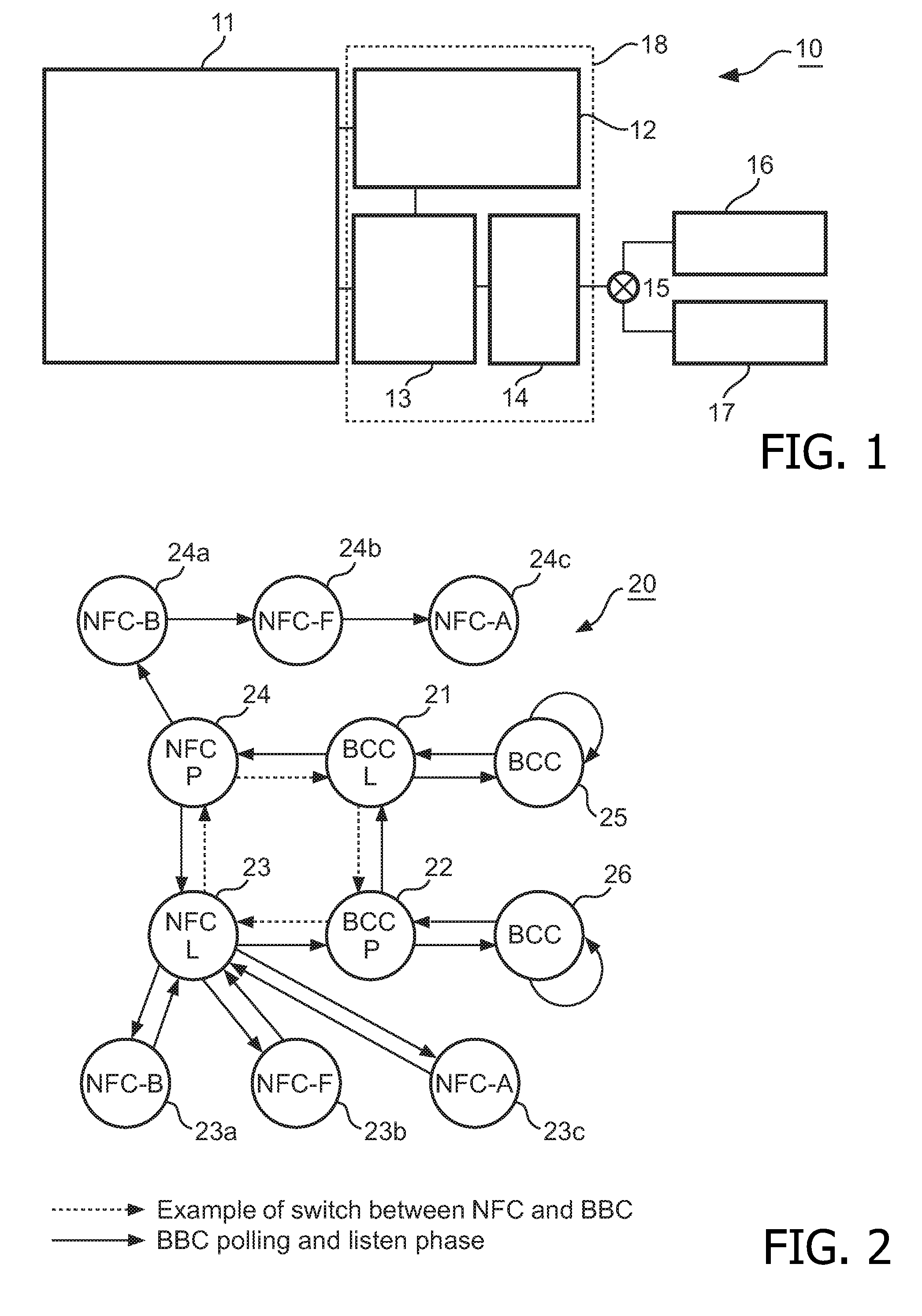
[0036]FIG. 1 shows a schematic configuration of a device, i.e. a hardware module 10, according to an embodiment. A transmission module 11 performs a generation of a transmitted signal. This signal can be an authentication signal, a session signal or a data signal. The transmission module 11 can be coupled to any sending device, requesting device and / or receiving device. In the exemplary hardware module 10 depicted in FIG. 1, the transmission module 11 is connected to a receiver circuit 12. The receiver circuit 12 provides a received signal to an internal receiving stage of the transmission module 11. A filter 13 is connected to the transmission module 11 and to the receiver circuit 12. The filter 13 is configured to reduce the harmonics of the transmitted signal and perform an impedance transformation, if necessary. The filter 13 can be an electromagnetic compatibility (EMC) filter or any other filter capable of reducing harmonics and / or impedance transformation. In the exemplary ha...
PUM
 Abstract
Description
Claims
Application Information