Huber needle safety enclosure

a safety enclosure and needle technology, applied in the field of safety enclosures for hypodermic needles, can solve the problems of natural bounce back of needles, increased risk of needle removal at the end of infusion therapy, and increased risk of needle slipping, so as to prevent the needle from rocking

Active Publication Date: 2010-12-09
CR BARD INC
View PDF71 Cites 13 Cited by
  • Summary
  • Abstract
  • Description
  • Claims
  • Application Information

AI Technical Summary

Benefits of technology

[0014]A further embodiment of the present invention is where the first basic embodiment is modified by the needle housing including an enlarged finger pad with the enlarged finger pad to provide a flat surface facilitating application of manual pressure that is necessary to install the Huber needle and also for practitioner comfort.
[0016]A further embodiment of the present invention is where the just previous embodiment is modified by having the handle extend to a lower position which is to rest on the skin of the patient to prevent rocking movement of the needle when installed in the port.
[0028]A further embodiment of the present invention is where the second basic embodiment is modified by having the gripping handle extend to a lower position which is to rest on the skin of the patient and prevent rocking movement of the needle.
[0029]A third basic embodiment of the present invention is directed to a Huber needle safety enclosure which has a Huber needle mounted within a needle housing with this Huber needle having a sharp outer end. A panel unit is composed of a series of edge connected sheet material panels assembled in an enclosing arrangement defining an enclosed area with each of the panels being hingedly movable to a pair of the panels. The panel unit is movable between a installation position where the sharp outer end projects from the panel unit and a safety position where the sharp outer end is covered by the panels. The panel unit has side edges when in the installation position with each side edge including an elongated protuberance which functions as a guide to assist the user as to where squeezing manual pressure is to be applied to move the panel unit from the installation position to the safety position.

Problems solved by technology

Because of this ninety degree bend configuration of the needle, removing the needle at the end of the infusion therapy is particularly dangerous to the medical practitioner.
This danger has to do with applying an outward force to the needle, and when the needle is exterior of the port, there is a natural bounce-back of the needle.
As a result, the medical practitioner may be subjected to the same infection that the patient is subjected to.
However, the implanted port has one significant disadvantage and that there is a high degree of needlestick injury during removal of the Huber needle by the practitioner.
In the past, a needlestick injury has been attributed to carelessness on the part of the medical practitioner.
In actuality, carelessness has little to do with needlestick injuries as it is directly related to the difficulty of removing the needle.
Inherently, the procedure of removing of a Huber needle results in bounce-back which comprises a rebounding effect.
This hooking of the needle is due to a snag occurring impeding the removal of the needle from the septum.
When the needle is finally released, the muscles relax and an opposite movement takes place and drives the Huber needle point down into the non-dominant hand of the medical practitioner thus causing the common form of needlestick injury.
There are certain deficiencies in the product of this prior patent.
The prior product had a tendency to move to the safety position inadvertently, like when a patient would roll over on his or her side.
This is not desirable as the needle is automatically withdrawn from the port.
This caused a certain amount of instability making it difficult for the medical practitioner to manipulate and install the needle.
Also, the needle would have a tendency to rock longitudinally in position and eventually would withdraw itself from the access site.
Ergonomically, the housing of the prior art product did not have any finger pads that facilitated the location of the medical practitioner's fingers that would assist in installing the needle.
The panel unit within the prior art product did not have a smooth surface that would be in contact with the patient's skin which had a tendency to be uncomfortable to the patient.
Also, there was no ventilation structure within the prior art product which would tend to eliminate sweating by the patient in the area of the installed enclosure.
There was no structure in the prior art product that assisted in retaining the needle in position relative to the panel unit (wings) during assembly.

Method used


Image

  • Huber needle safety enclosure
  • Huber needle safety enclosure
  • Huber needle safety enclosure

Examples


Embodiment Construction

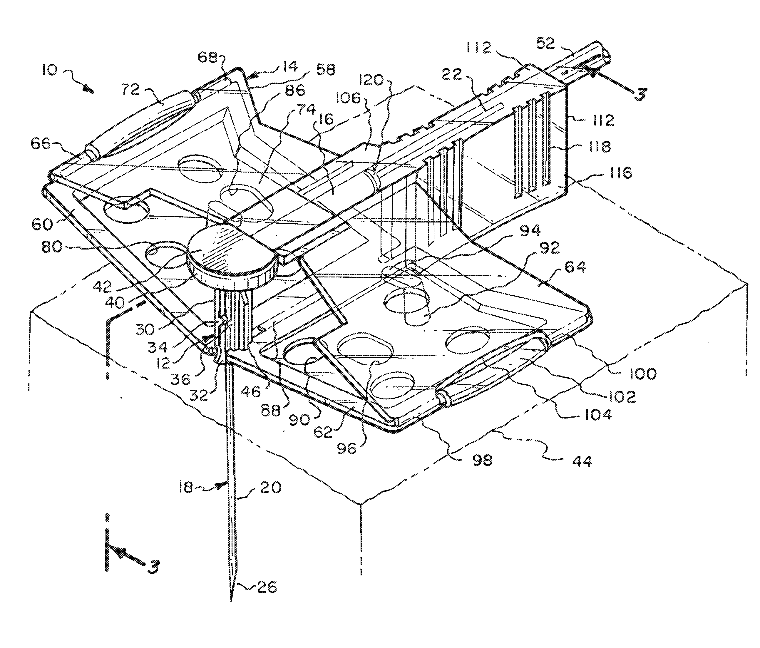
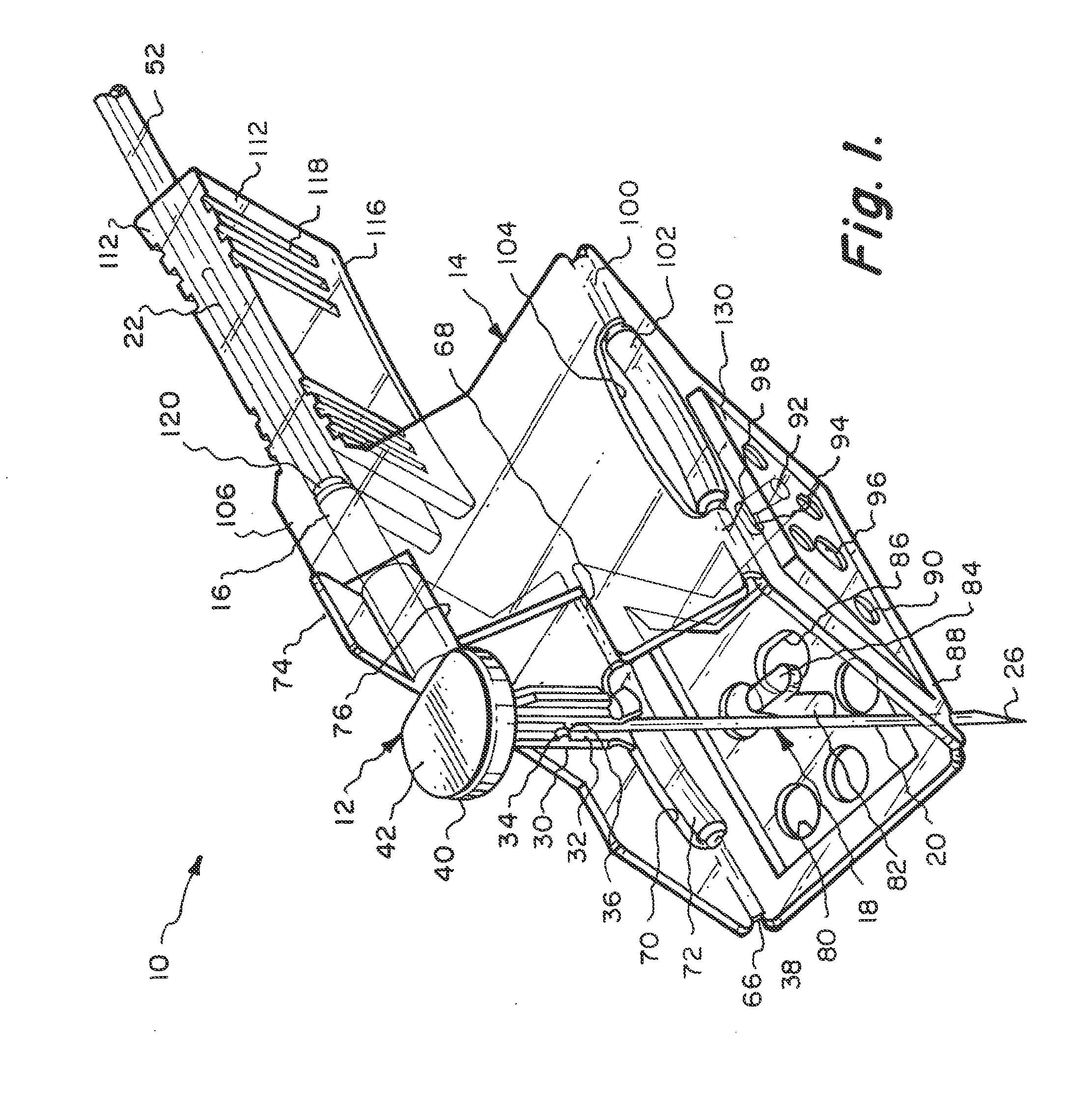
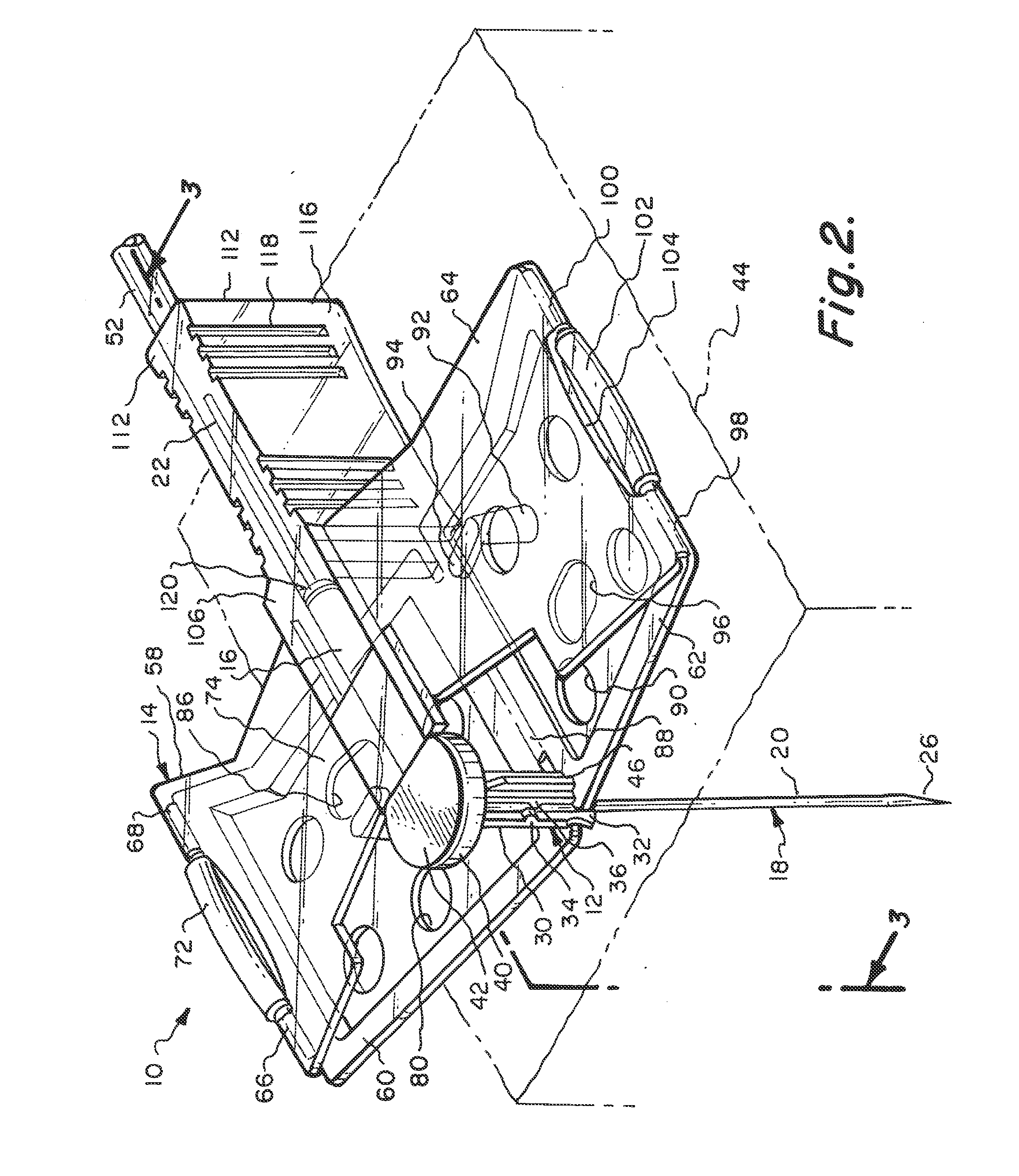
[0045]Referring particularly to the drawings, there is shown the Huber needle safety enclosure 10 of this invention. The safety enclosure 10 includes, generally, a needle housing 12 and a panel unit 14. The needle housing 12 includes an elongated cylindrical hinge tube 16 which is constructed of plastic as well as almost all of the components of this enclosure 10. The only part that is not constructed of plastic will be the Huber needle 18 itself, which will be constructed of metal.

[0046]The Huber needle 18 is in the shape of a right angle and has a fore end 20 and an aft end 22. The fore end 20 is connected to the aft end 22 at a bend 24. The free end of the fore end 20 is formed into a sharpened tip 26. The hinge tube 16 has a through passage 28. The aft end 22 of the Huber needle 18 is located in a close fitting but yet slidable manner within the through passage 28. Integrally connected to the hinge tube 16 at 20 its front end is a sleeve 30. Longitudinally formed within the slee...


PUM


Abstract

A safety enclosure for a Huber needle includes a needle housing and a panel unit. The panel unit includes a series of planar panels assembled in an enclosing arrangement defining an enclosed area and is movable between an installation position where the sharp outer end of the Huber needle projects from the panel unit and a safety position where the sharp outer end is covered by the panels. The Huber needle has an aft end and a fore end connected by a bend with the fore end including a sharp outer end.

Description

PRIORITY[0001]This application is a continuation of U.S. patent application Ser. No. 10 / 787,605, filed Feb. 26, 2004, now U.S. Pat. No. 7,776,016, which is incorporated by reference in its entirety into this application.FIELD OF THE INVENTION[0002]This invention is directed to a safety enclosure for a hypodermic needle known as a Huber needle and more particularly to improvements over a prior art type of safety enclosure which is defined within U.S. Pat. No. 5,951,522, entitled HYPODERMIC NEEDLE SAFETY ENCLOSURE, issued Sep. 14, 1999, and which is incorporated by reference in its entirety into this application.DESCRIPTION OF THE RELATED ART[0003]Within the medical field, some patients require the use of a vascular access device as part of his or her care. A vascular access device is used on a patient to provide pain drugs, chemotherapy, antibiotics, antiviral or antifungal drugs as well as for hydration and nutrition. In recent years, there has been a substantial increase in the num...

Claims


Application Information

Patent Timeline
Patent Type & Authority Applications(United States)
IPC IPC(8): A61M5/42A61M5/00
CPCA61M5/158A61M5/3275A61M2005/1581
Inventor HALSETH, THOR R.BARKER, JOHN M.
Owner CR BARD INC
Why Eureka
Try Eureka