Supercharge Your Innovation With Domain-Expert AI Agents!

Method for coating prosthesis elements and elements obtainable with the method

a technology of prosthesis and coating, which is applied in the field of coating prosthesis elements and elements obtainable with the method, can solve the problems of affecting the life span of the prosthesis, the diameter of the spherical head of the other side of the prosthesis must be limited, and the overall strength of the prosthesis to be affected

Inactive Publication Date: 2010-12-09
EUROCOATING
View PDF2 Cites 3 Cited by
  • Summary
  • Abstract
  • Description
  • Claims
  • Application Information

AI Technical Summary

Benefits of technology

[0020]Another object of the invention is to create a method for coating prosthesis elements and elements obtainable with the method that allow making prostheses that are strong and lightweight.
[0021]A further object of the invention is to create a method for coating prosthesis elements that allows making prostheses that do not generate movements between these and the bone parts to which they are applied or with which they are in contact.
[0023]Another object of the invention is to create a method for coating prosthesis elements and elements obtainable with the method that allow obtaining prostheses able to keep the bone parts to which they are applied under stress, preventing the harmful shrinking of such parts.
[0030]to make prostheses that allow discharging the stress transmitted by the legs onto the bone tissue as well, keeping this active and therefore voluminous enough so as not to create, over time, reductions in volume and the consequent occurrence of clearances between the prosthesis and the replaced bone portion.

Problems solved by technology

Because this joint has to withstand all the loads transmitted to the pelvis by the legs, the prostheses must have a limited friction between the two components in reciprocal contact and must be very strong and fixable to the respective bone portions in a stable way, without any micro movements occurring between one of the components and the bone portion to which this is associated: in fact, these micro movements are very damaging for the life span of the prosthesis.
A first drawback is that because of the considerable thickness of the coating of the cotyle concavity, the diameter of the spherical head of the other side of the prosthesis must necessarily be limited.
Another drawback is that this limitation of the diameter of the spherical head on the one hand limits the overall strength of the prosthesis due to a reduced supporting surface between the spherical head of the thigh bone and the cotyle concavity and, finally, the amount of load the prosthesis can withstand and, on the other hand, considerably increases the friction between the two surfaces in reciprocal contact, determining substantially quick wear of the cotyle coating and the risk of the prosthesis becoming blocked.
A further drawback is that the diameter of the cotyle cannot be increased in order to also proportionately increase the diameter of the internal cavities of the cotyle in order to use heads of thigh bones with correspondingly larger diameters, because a cotyle with dimensions larger than those of known cotyles would be very hard to fit inside the cotyloid cavity and, in any case, an excessive diameter of this cotyle could stress the walls of the cotyloid cavity during fitting, even causing, at worst, the walls to fracture.
Another drawback is that the components of some of the known prostheses are too rigid and this results in the stresses made during walking being discharged onto the components of the prosthesis and not also distributed on the bone part to which the latter are fitted.
Consequently, the bone part, not being adequately stressed or being stressed to a small extent, tends to gradually reduce in volume, generating clearances over time, and, therefore, relevant movements between this and the parts making up the prosthesis.
This, with the passing of time, makes the fitting of the latter pointless.

Method used


Image

  • Method for coating prosthesis elements and elements obtainable with the method
  • Method for coating prosthesis elements and elements obtainable with the method
  • Method for coating prosthesis elements and elements obtainable with the method

Examples


Embodiment Construction

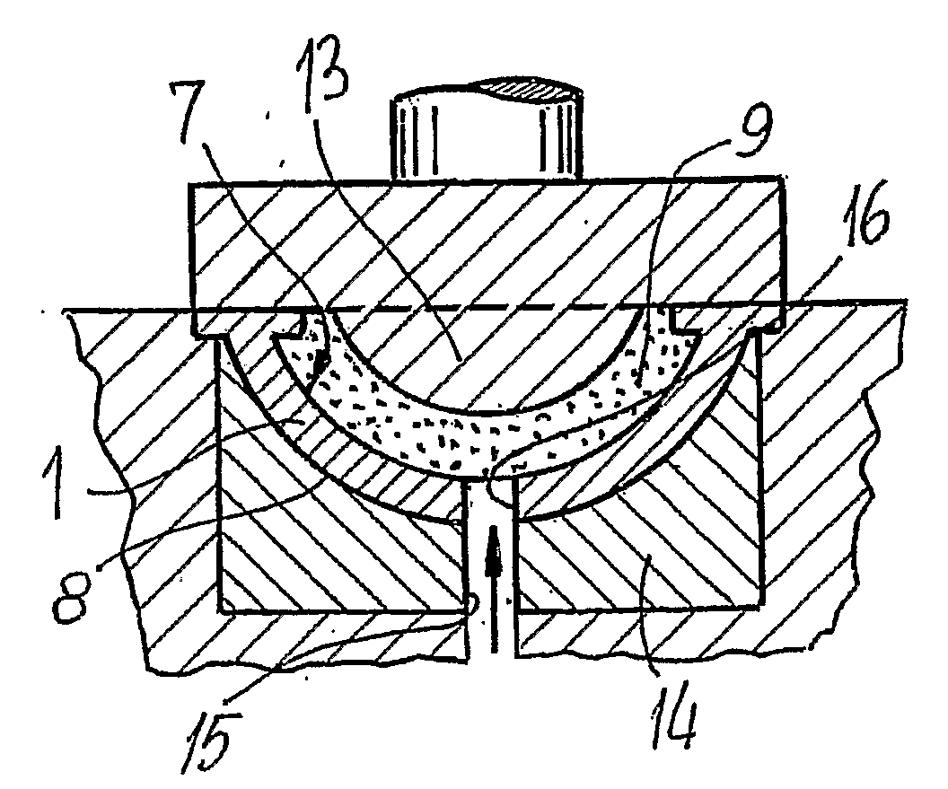
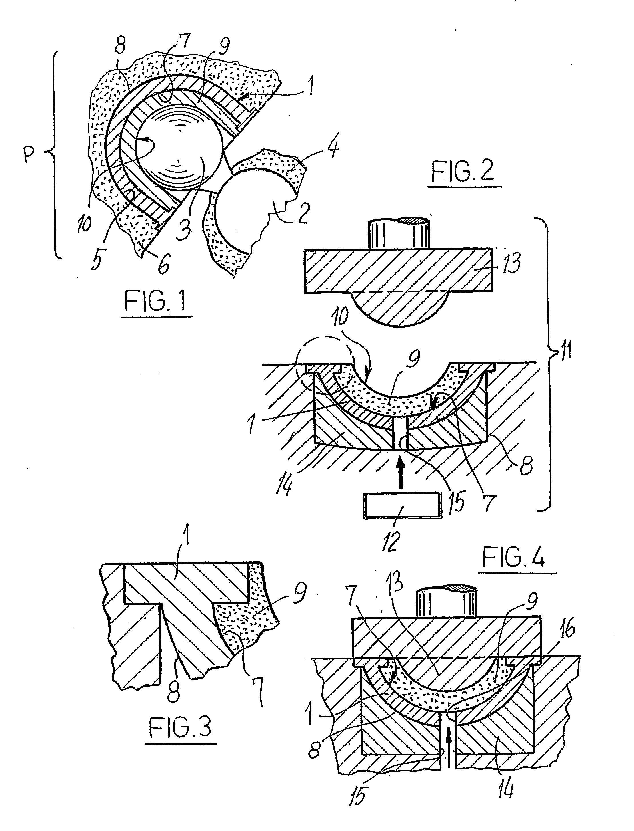
[0057]With reference to the Figures, by 1 is generically indicated a cup cotyle, normally shaped like a sphere, to form a prosthesis “P”, which also comprises a portion 2 having a spherical head 3, or substantially such, and which can be applied on a thigh bone 4, which can be coupled with the cotyle 1 to replace the joint of a hip.

[0058]The cotyle 1, which is to be fitted and fixed inside the cotyloid cavity 5 of a hip 6, defines a concave surface 7 and a convex counter surface 8.

[0059]The concave surface 7 can be coated with a layer 9 of polymer material which defines a face 10, also concave, with a low friction coefficient and which is to come into contact with the spherical head 3 of the portion 2.

[0060]To make the layer 9, the polymer material is prepared in such a state as to make it mouldable, meaning, in effect, in a state chosen from liquid, fluid or pasty, so that it can shape itself automatically on the concave surface 7.

[0061]According to the method for coating prosthesi...


PUM

PropertyMeasurementUnit
friction coefficientaaaaaaaaaa
45° anglesaaaaaaaaaa

Abstract

A method for coating prosthesis elements that have a concave surface and a corresponding convex counter surface includes arranging in at least the concave surface a shaped retention surface for gripping a coating. The coating is coupled with the shaped retention surface such that coupling includes coating the concave surface with the coating temporarily in a moldable state to obtain a moldable coating. The moldable coating is made to solidify and adhere firmly to the shaped retention surface.

Description

TECHNICAL FIELD[0001]The invention relates to a method for coating prosthesis elements and elements obtainable with the method, particularly suitable for the coupling of resistant-to-wear polymer components and metal components for articulate prostheses, in detail for making prostheses for replacing the joint of a hip.STATE OF THE ART[0002]Prostheses are known for replacing the hip joint in patients suffering from serious illnesses, such as, for example, arthrosis or arthritis, or who have suffered fractures that do not permit spontaneous bone reconstruction by simple immobilisation of the pelvis and of the thigh bone.[0003]These prostheses comprise a first portion that must be implanted in a longitudinal direction in the thigh bone and which forms an end turned towards the pelvis shaped like a sphere or the like, which practically reproduces the head of the thigh bone, and a second portion shaped like a cup and called cotyle, which is arranged in the cotyloid cavity of the hip, mea...

Claims


Application Information

Patent Timeline
Patent Type & Authority Applications(United States)
IPC IPC(8): A61F2/32B05D7/00B05D5/00
CPCA61F2/30767A61F2/3094A61F2/34A61F2002/30179A61F2002/30841A61F2002/3403A61F2002/3412A61F2002/342A61F2002/349A61F2230/0058B29C37/0082B29C45/14311B29C2045/14327B29L2031/7532
Inventor ANTOLOTTI, NELSOMAGALINI, EMANUELE
Owner EUROCOATING
Features
  • R&D
  • Intellectual Property
  • Life Sciences
  • Materials
  • Tech Scout
  • Unparalleled Data Quality
  • Higher Quality Content
  • 60% Fewer Hallucinations
Learn More