Computer system managing I/O path and port

a computer system and i/o path technology, applied in computing, error detection/correction, instruments, etc., can solve the problems of inability to execute failover while the device is running, inability to manage the i/o path and port, and the switch host is inevitably accompanied by resetting and re-initialization. achieve the effect of high reliability

Inactive Publication Date: 2010-12-09
HITACHI LTD
View PDF50 Cites 56 Cited by
  • Summary
  • Abstract
  • Description
  • Claims
  • Application Information

AI Technical Summary

Benefits of technology

[0017]The multiple virtual switches are provided, and switching between the virtual switches can be made without resetting any relevant I / O device, which prevents an active computer from presenting the single point of failure. A computer system that is highly reliable overall can thus be built.

Problems solved by technology

While the CPU performance has improved, there has been a shortage of I / O devices which require connectors and ports for input and output.
With this method, however, dealing with a failure requires the re-assigning of bus numbers and similar procedures that make it difficult to execute failover while the devices are running.
With this method, however, switching hosts is inevitably accompanied by resetting and re-initialization.

Method used


Image

  • Computer system managing I/O path and port
  • Computer system managing I/O path and port
  • Computer system managing I/O path and port

Examples


first embodiment

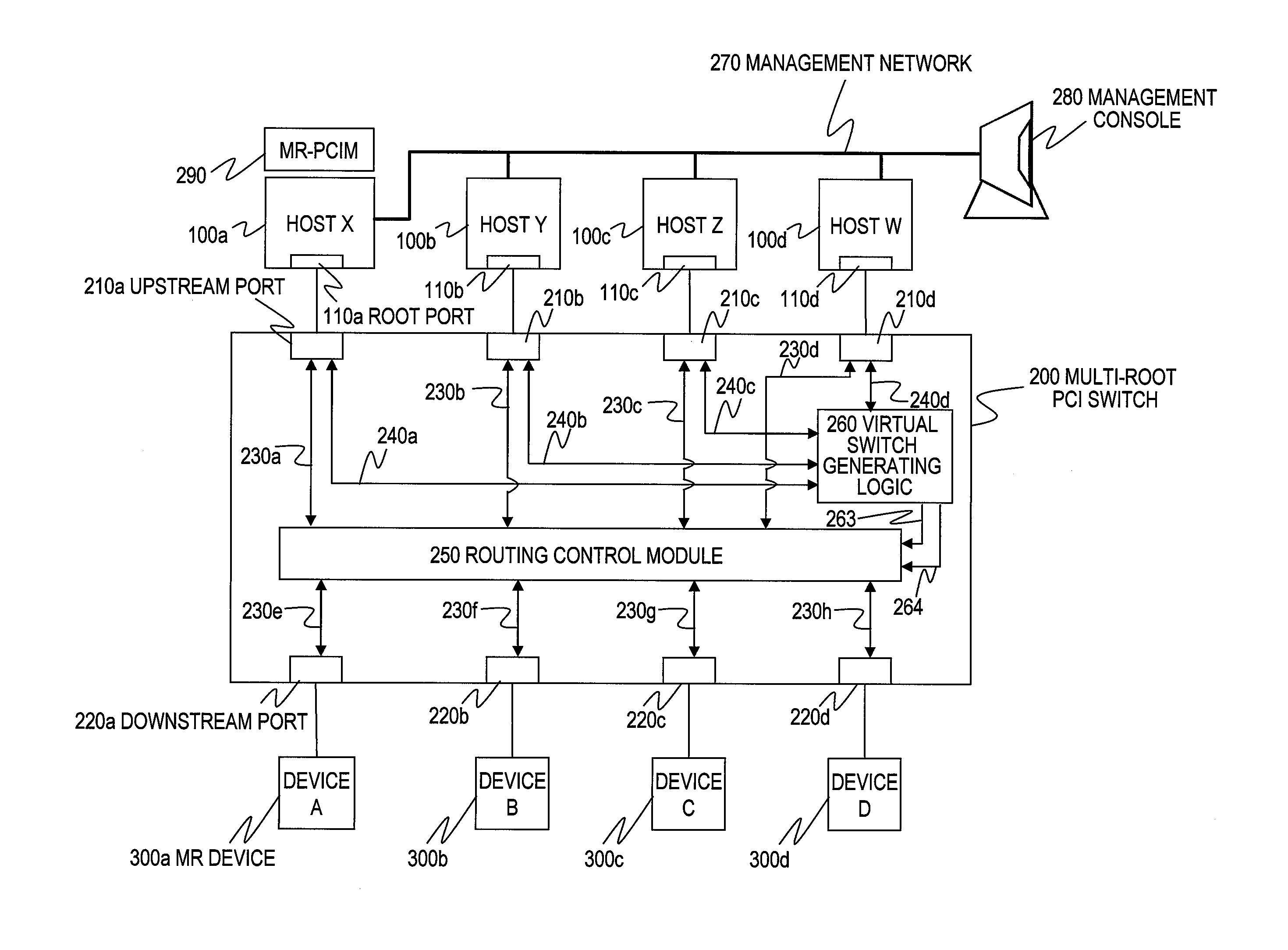
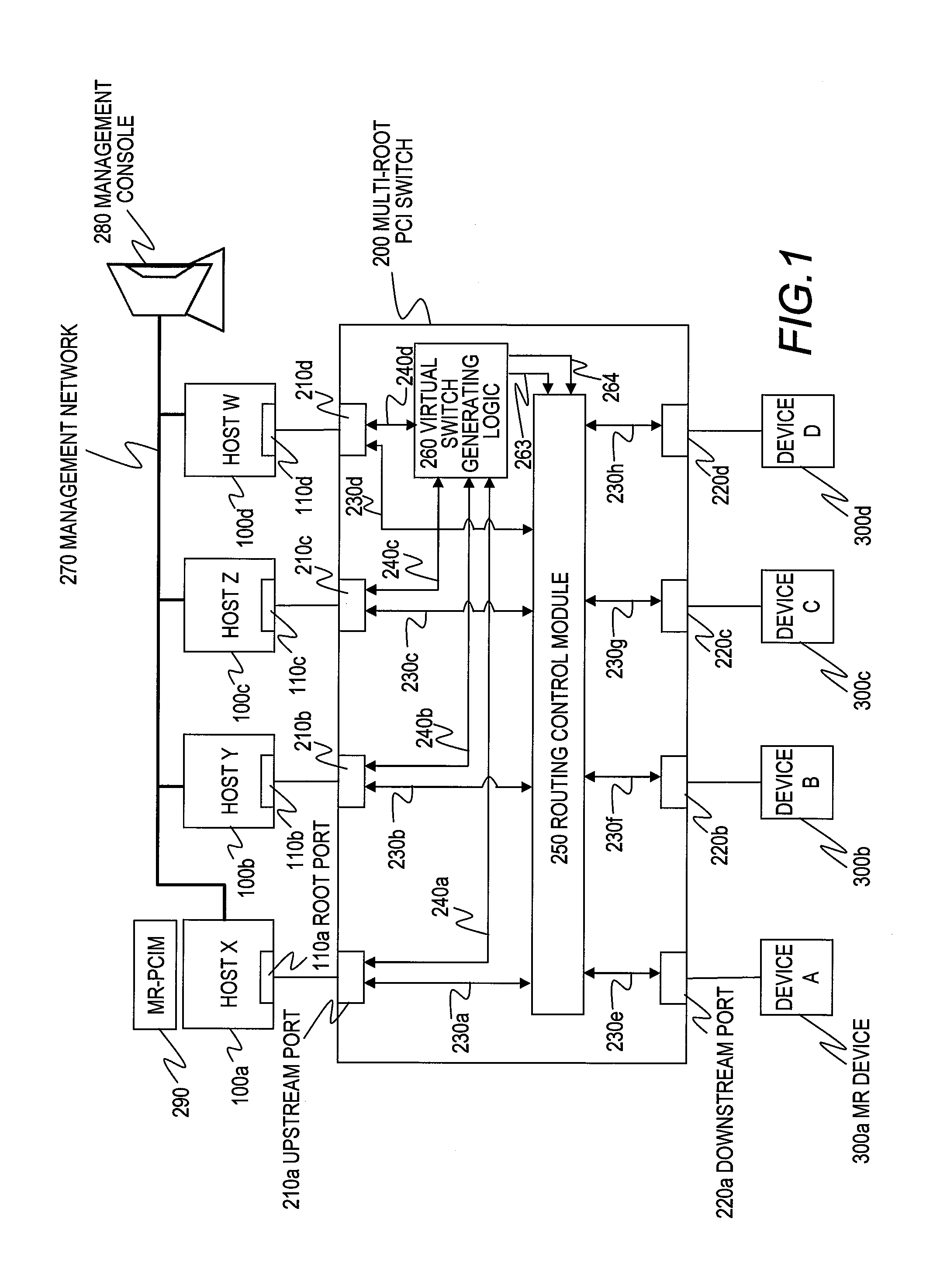
[0046]FIG. 1 is a block diagram illustrating an example of a configuration of a computer system according to a first embodiment of this invention.

[0047]The computer system includes hosts 100a to 100d, multi-root I / O devices (hereinafter, also referred to as MR devices) 300a to 300d, which are used by the hosts 100a to 100d, and a multi-root PCI switch 200, which connects the hosts 100a to 100d and the MR devices 300a to 300d to each other.

[0048]When there is no particular need to distinguish one from another, the hosts 100a to 100d are each referred to as host 100 and the MR devices 300a to 300d are each referred to as MR device 300.

[0049]A PCI manager 290 which manages the multi-root PCI switch 200 and the MR devices 300 is run on the host 100a.

[0050]The hosts 100a to 100d are connected to one another via a management network 270. A management console 280 is connected to the management network 270, enabling an administrator to manage the PCI manager 290 through the management cons...

modification example

of the First Embodiment

Takeover Upon Failure (=Failover)

[0191]A modification example of the first embodiment of this invention is described next.

[0192]A difference between this modification example and the first embodiment is when to execute failover to the backup host Y (100b). Specifically, in the modification example of the first embodiment, the backup host Y (100b) detects a failure in the active host X (100a) and the detection of the failure triggers the execution of failover.

[0193]A computer system in the modification example and its components including the hosts 100 and the multi-root PCI switch 200 have the same configurations as those in first embodiment. Descriptions on the components are therefore omitted here, and the focus is placed on differences from the first embodiment in the following description.

[0194]FIG. 21 is a flow chart illustrating processing of takeover upon failure according to the modification example of the first embodiment of this invention.

[0195]The a...

second embodiment

[0204]A second embodiment of this invention is described below.

[0205]A computer system in the second embodiment and its components including the hosts 100 and the multi-root PCI switch 200 have the same configurations as those in first embodiment. Descriptions on the components are therefore omitted here, and the focus is placed on differences from the first embodiment in the following description.

[0206]In the second embodiment, new items are added to the virtual switch group management table 510.

[0207]FIG. 22 is an explanatory diagram illustrating a virtual switch group management table 510-2 according to the second embodiment of this invention.

[0208]As shown in FIG. 22, failure settings 540 are newly added to each entry in the virtual switch group management table 510-2.

[0209]The failure settings 540 are made up of itemized settings for automatically switching the virtual switches 400 upon detection of a failure by the multi-root PCI switch 200. Details of the failure settings 540...


PUM


Abstract

It is provided a computer system comprising a plurality of computers; a PCI switch; and a plurality of I/O devices connected to the PCI switch, wherein the communication path includes a virtual switch and virtual bridges, and the PCI switch comprises a communication path generating module for setting the virtual switches and the virtual bridges, a virtual switch group management module for creating a virtual switch group including the at least one of the virtual switches, and setting an enabled flag to one of the virtual switches included in the virtual switch group, and a port management module for managing relation between each of the generated communication paths and the plurality of ports included in the each of the generated communication paths.

Description

CLAIM OF PRIORITY[0001]The present application claims priority from Japanese patent application JP 2009-134682 filed on Jun. 4, 2009, the content of which is hereby incorporated by reference into this application.CROSS REFERENCE TO RELATED APPLICATIONS[0002]This application claims the benefit of the following applications filed in the United States Patent and Trademark Office, U.S. patent application Ser. No. 12 / 546,264 entitled “COMPUTER SYSTEM AND METHOD FOR SHARING PCI DEVICES THEREOF”, filed on Aug. 24, 2009, and U.S. patent application Ser. No. 12 / 709,405 entitled “COMPUTER SYSTEM, METHOD OF MANAGING PCI SWITCH, AND MANAGEMENT SERVER”, filed on Feb. 19, 2010, the disclosures of all of which are herein incorporated by reference in their entireties.BACKGROUND OF THE INVENTION[0003]This invention relates to a multi-computer system in which a plurality of computers and a plurality of PCI devices are connected by a PCI switch, and more particularly, to enhancing the reliability of a...

Claims


Application Information

Patent Timeline
Patent Type & Authority Applications(United States)
IPC IPC(8): G06F13/00
CPCG06F13/387G06F2213/4004
Inventor UEHARA, KEITAROBABA, TAKASHIGETSUSHIMA, YUJI
Owner HITACHI LTD
Why Eureka
Try Eureka