Snare tension device

Active Publication Date: 2010-12-16
GEWA MUSIC
View PDF12 Cites 4 Cited by
  • Summary
  • Abstract
  • Description
  • Claims
  • Application Information

AI Technical Summary

Benefits of technology

[0010]Such a structure comprises the advantage that there is no risk anymore that the snare wire can automatically and unintentionally loose and release again by means of the tensile force which is exerted to the rotation unit by the snare wire. Thus, in a tensioned state of the snare tension device, there is no necessity to provide a locking device for the rotation unit, which locking device prevents an unintentional reverse movement of the rotation unit into a released position. In the end, an omission of the locking device results in a reduction of the manufacturing costs of the snare tension device. Additionally, the handling of the snare tension device is simplified for the user because the user does not need to operate a locking device.
[0011]In addition, there is a further advantageous embodiment of the invention that the usage of a rotatin

Problems solved by technology

The known snare tension device comprises several disadvantages by providing the groove in the pushing element in which groove the projection of the lever is guided.
There is a disadvantage that dirt can accumulate within the groove so that a movement of the projection or rather the lever is hindered within the groove.
Additionally, when the snare tension device is

Method used


Image

  • Snare tension device
  • Snare tension device
  • Snare tension device

Examples


Example

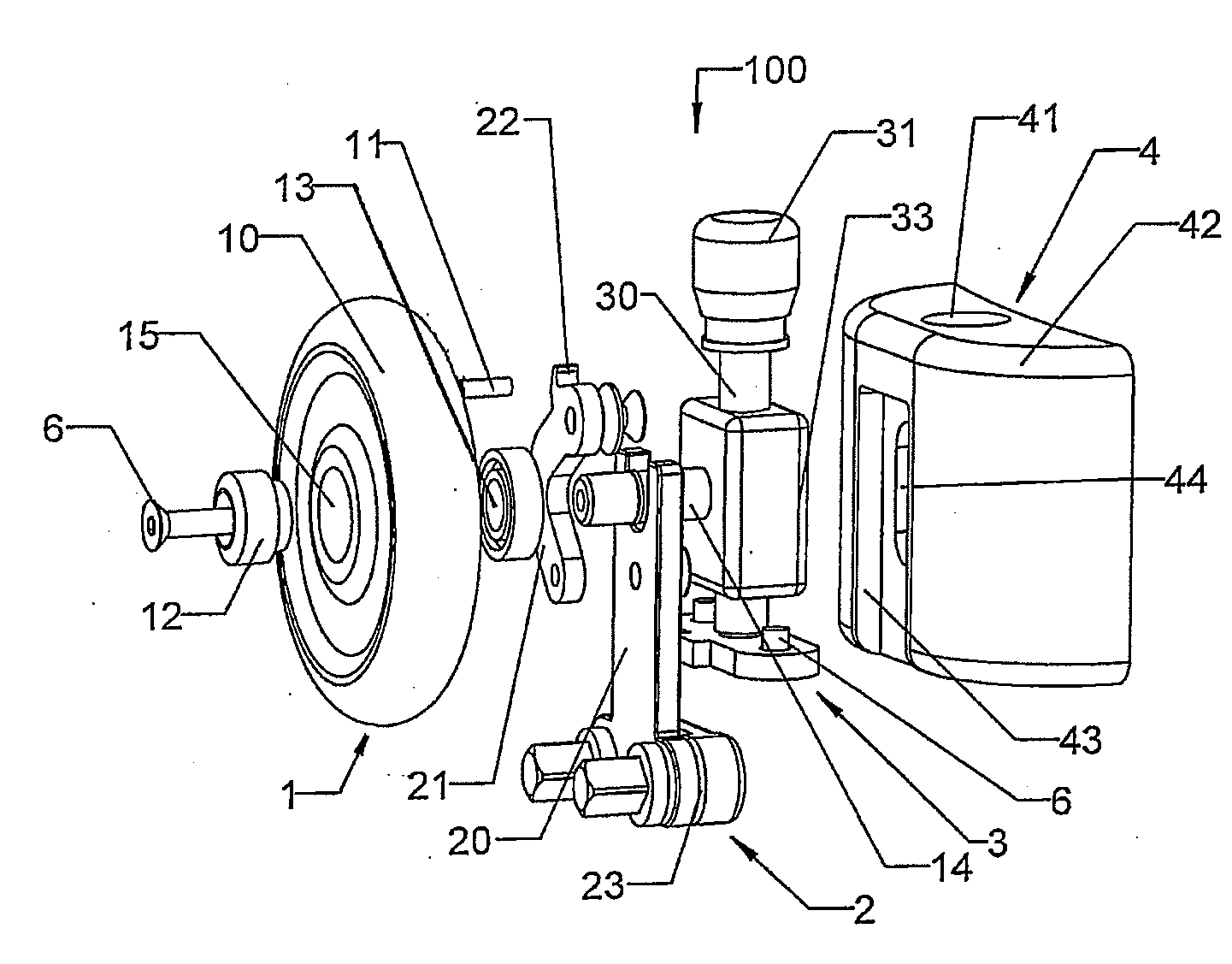
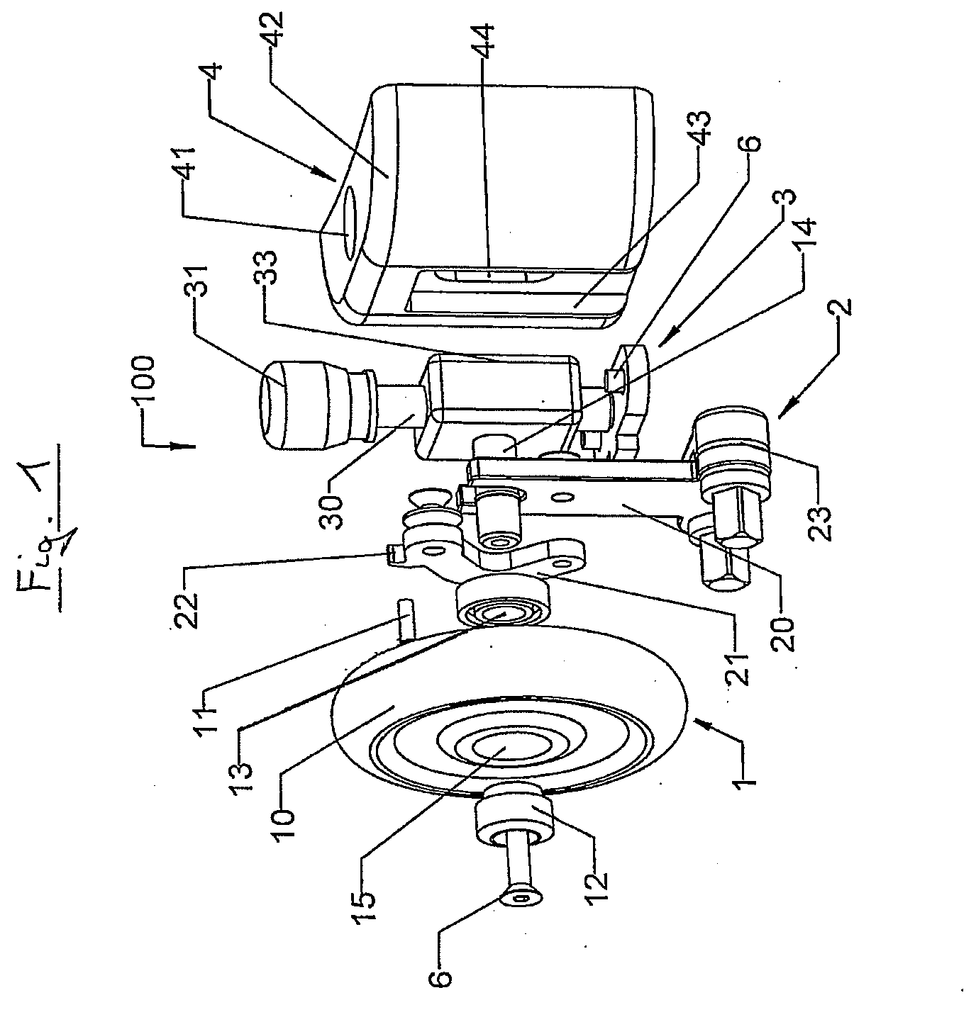
[0021]The snare tension device 100 shown in FIG. 1 comprises a rotation unit 1, a transfer unit 2, an adjustment device 3 and a snare tension housing 4.

[0022]The rotation unit 1 comprises a rotation element 10 that is e.g. formed as a rotating wheel in the present embodiment. The rotation element 10 comprises an aperture 15 at its center in which a ball bearing 13 and a sleeve 12 are insertable. The sleeve 12 comprises two portions with different outer diameters. The first portion distant to the transfer unit 2 has an outer diameter, which corresponds with the inner diameter of the aperture 15 of the rotation element 10. The second portion of the sleeve 12 facing to the transfer unit 2 has a diameter corresponding with an inner diameter of an aperture arranged in the ball bearing 13. Additionally, the sleeve 12 comprises an aperture in which a fixing means 6 can be inserted. Here, for example, the fixing means 6 is a screw. Furthermore, the rotation unit 1 comprises a pin 11, which ...


PUM


Abstract

The invention relates to a snare tension device for tensioning and releasing a snare wire. In the snare tension device a rotation movement of a rotation element is transferred to a pushing element by means of a transfer element.

Description

CROSS-REFERENCE TO RELATED APPLICATIONS[0001]This application is related to and claims the benefit of priority from, German Patent Application Serial Number 10 2009 024908.7, filed 15 Jun. 2009, the disclosure of which is incorporated by reference in its entirety.FIELD OF INVENTION[0002]The invention relates to a snare tension device for tensioning and releasing a snare wire at a snare.BACKGROUND OF INVENTION[0003]Snare tension devices for tensioning and releasing a snare wire are already known from the prior art. U.S. Pat. No. 7,220,905 B2 discloses a snare tension device for tensioning and releasing the snare wire at a resonance skin of a snare. Specifically the tensioning and releasing of the snare wire is carried out by means of a lever which is rotatable around a fulcrum. The lever comprises a projection in a section spaced apart from the fulcrum, which projection is guided in a groove of a pushing element, in an range distant to the fulcrum. The projection is arranged with res...

Claims


Application Information

Patent Timeline
IPC IPC(8): G10D13/02
CPCG10D13/025G10D13/18G10D13/02
Inventor HOLL, WINFRIEDSTEINHAUSER, RUBEN
Owner GEWA MUSIC
Why Eureka
Try Eureka