
Bus support system for a motor conrol center

a bus support and motor technology, applied in the direction of machine supports, snap fasteners, connection contact material, etc., can solve the problems of high short circuit current level of bus bars, high cost of manufacturing such a bus support system, and the need for specially designed bus support structures with extensive bracing

Active Publication Date: 2010-12-16
ROCKWELL AUTOMATION TECH
View PDF12 Cites 20 Cited by
  • Summary
  • Abstract
  • Description
  • Claims
  • Application Information

AI Technical Summary

Benefits of technology

[0008]In accordance with another aspect, a motor control center is provided. The motor control center includes vertical and horizontal bus conductors disposed within an electrical enclosure and a bus support configured to support the vertical and horizontal bus conductors, wherein the bus support comprises a plurality of vertical channels configured to receive the vertical bus conductors, each of the plurality of vertical channels having a rear protrusion on a rear side of the bus support. The motor control center also includes a plurality of add-on bus support braces disposed on the rear side of the bus support and configured to contact the plurality of vertical channels to limit a movement of the vertical bus conductors during a high current event. In addition, the motor control center also includes a bus cover configured to cover the bus support and the vertical and horizontal bus conductors, the bus cover including openings for connecting electrical components to the vertical and horizontal bus conductors.

Problems solved by technology

Therefore, high short circuit current levels in the bus bars may require specially designed bus support structures with extensive bracing to withstand the high current levels.
However, costs of manufacturing of such bus support system may be substantial.
However, this results in use of more material and expanded inventories, thereby substantially increasing the cost of the support system.
Moreover, because fewer of the higher rated systems are typically made, the higher rated bus support systems do not benefit from the same economy of scale as do the lower rated support systems.

Method used


Image

  • Bus support system for a motor conrol center
  • Bus support system for a motor conrol center
  • Bus support system for a motor conrol center

Examples


Embodiment Construction

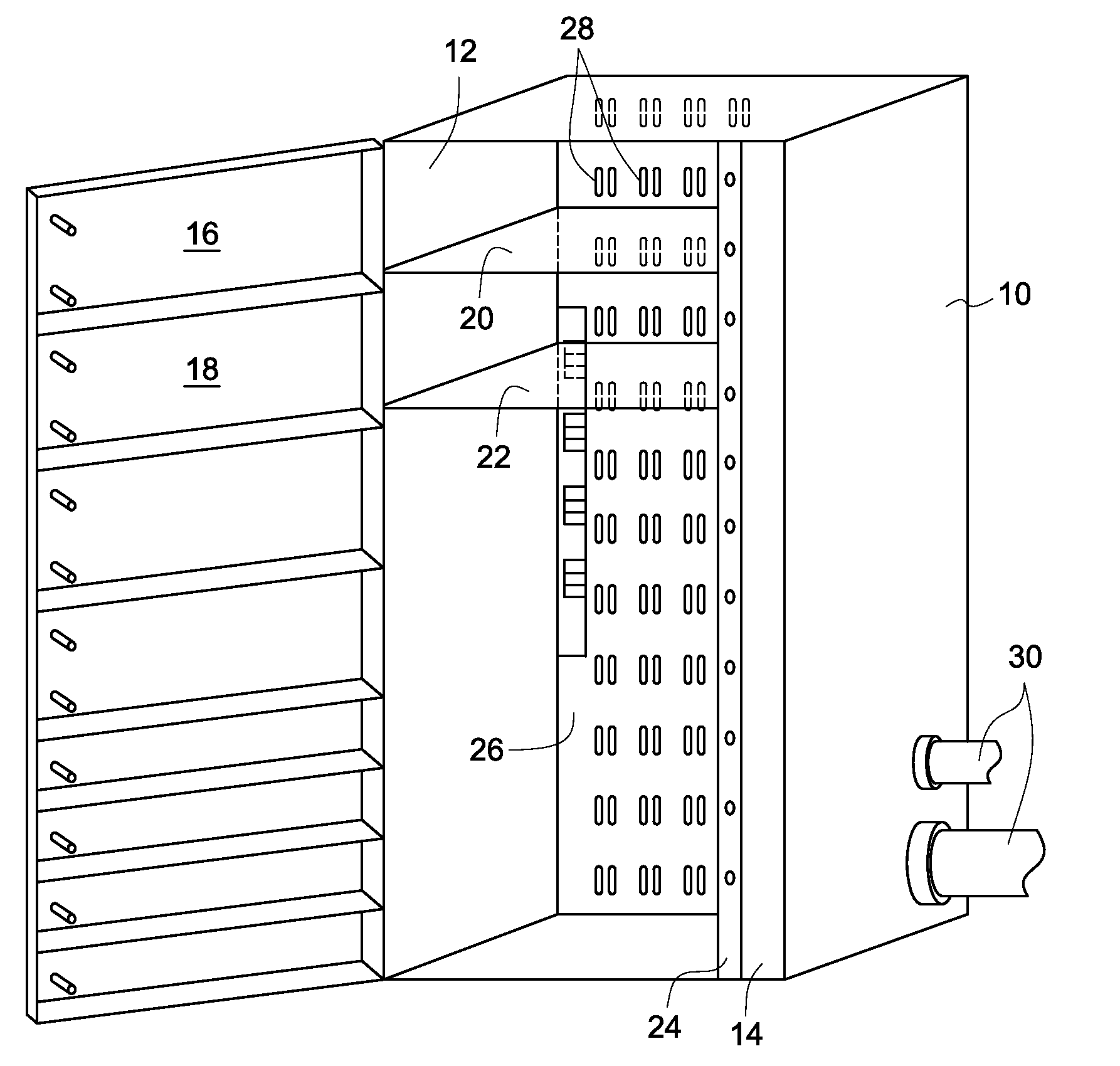
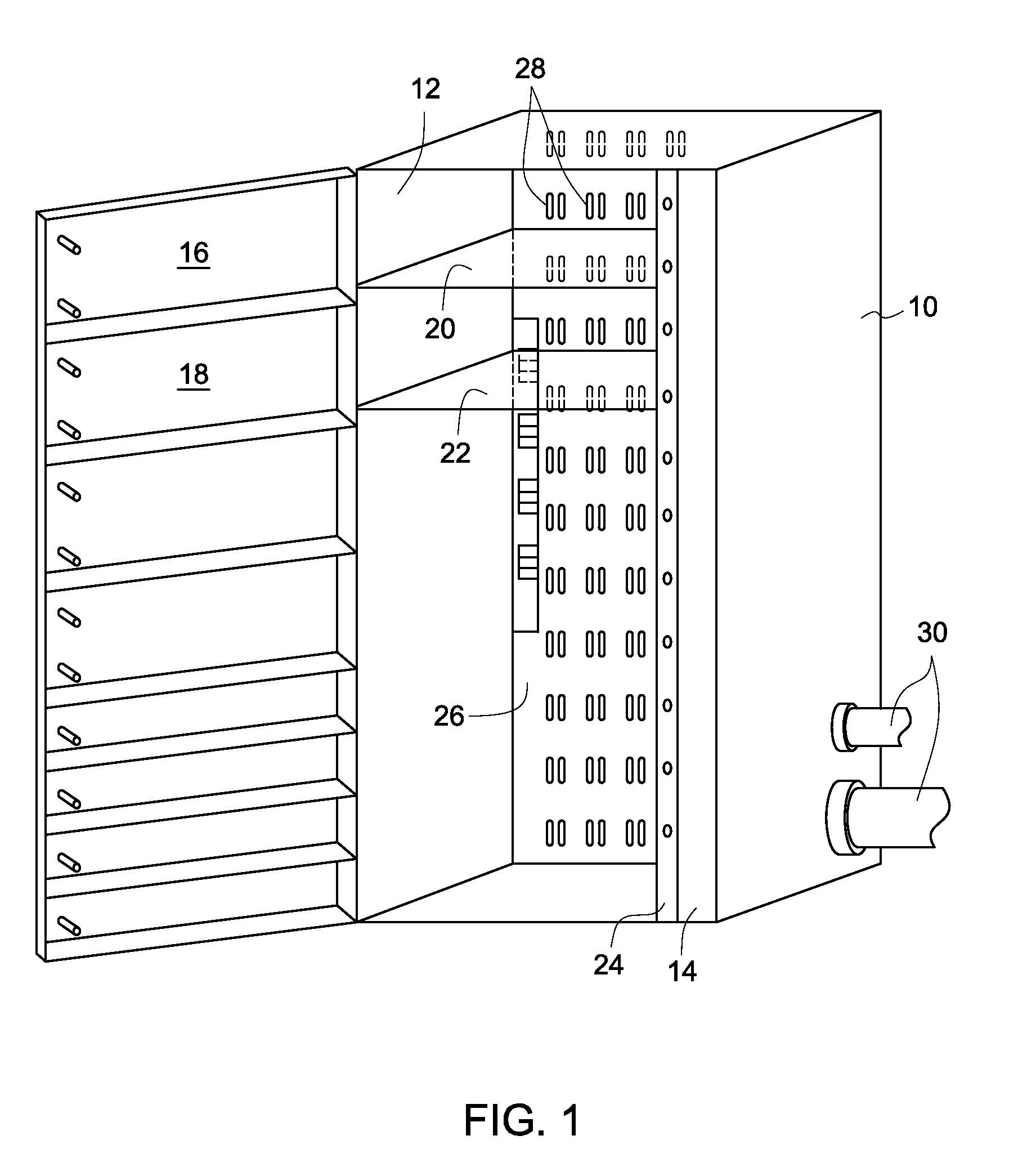
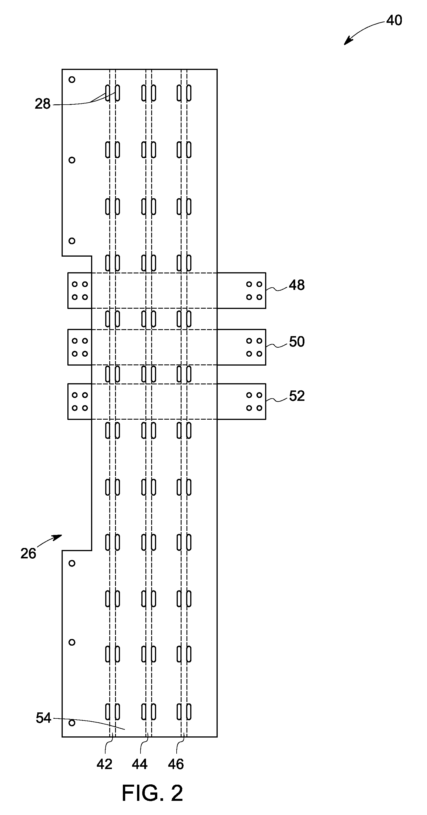
[0020]As discussed in detail below, embodiments of the present technique function to provide a bus support system for an electrical enclosure such as for a motor control center. In particular, the present technique utilizes add-on bus support braces on the bus support system to limit movement of vertical bus conductors within the enclosure during a high current event.

[0021]References in the specification to “one embodiment”, “an embodiment”, “an exemplary embodiment”, indicate that the embodiment described may include a particular feature, structure, or characteristic, but every embodiment may not necessarily include the particular feature, structure, or characteristic. Moreover, such phrases are not necessarily referring to the same embodiment. Further, when a particular feature, structure, or characteristic is described in connection with an embodiment, it is submitted that it is within the knowledge of one skilled in the art to affect such feature, structure, or characteristic in...


PUM


Abstract

A bus support system is provided. The bus support system includes a bus support having a plurality of vertical channels configured to receive vertical bus conductors, each of the plurality of vertical channels having a rear protrusion on a rear side of the bus support. The bus support system also includes a plurality of add-on bus support braces disposed on the rear side of the bus support and configured to contact the plurality of channels to limit a movement of the vertical bus conductors during a high current event.

Description

BACKGROUND[0001]The present invention relates generally to electrical systems, such as for the distribution of power signals to controlled equipment, and particularly to a bus support system for such electrical systems.[0002]Electrical systems with packaged electrical and electronic components are known and are in use. For example, motor control centers (MCCs) are used for power and data distribution in large and industrial operations. In a motor control center, a variety of components such as switchgear, semiconductor power electronic circuits, programmable logic controllers, motor controllers, and so forth are housed in large electrical enclosures that may be subdivided into compartments.[0003]Typically, the MCC is connected to a main power line that feeds three-phase AC power into the MCC. The MCC includes associated bus bars, interconnections and supporting structures for distribution of electrical power to the various compartments. A typical arrangement includes vertical bus ba...

Claims


Application Information

Patent Timeline
IPC IPC(8): H02G5/06F16M13/00A44B21/00
CPCH02B1/21Y10T24/33
Inventor MALKOWSKI, JR., CHESTERMERIWETHER, JAMES H.
Owner ROCKWELL AUTOMATION TECH
Features
  • Generate Ideas
  • Intellectual Property
  • Life Sciences
  • Materials
  • Tech Scout
  • Unparalleled Data Quality
  • Higher Quality Content
  • 60% Fewer Hallucinations
Learn More