
Radiant module for a heating device for rooms, and method to produce said radiant module

a technology of radiant modules and heating devices, which is applied in the direction of metal-working equipment, stationary conduit assemblies, lighting and heating equipment, etc., can solve the problems of reduced heat exchange speed with ambient air, low heating efficiency, and relatively low flow of heated air, so as to increase the heat exchange speed and reduce the time for heating. , the effect of high speed

Inactive Publication Date: 2010-12-16
DE LONGHI SPA
View PDF10 Cites 0 Cited by
  • Summary
  • Abstract
  • Description
  • Claims
  • Application Information

AI Technical Summary

Benefits of technology

The present invention is a radiant module used in a device for heating rooms. It has two heat-conductor plates that are associated with each other to define a central portion where a heated fluid flows. The module has lateral walls that develop from the central portion and create a channel for the air to flow upwards and accelerate, resulting in a high-speed heat exchange with the ambient air and reducing the time for heating a room. The method for producing the module involves coupling the plates and shaping the first plate to create the channel. The invention also includes a heating device comprising multiple radiant modules.

Problems solved by technology

Known radiant modules therefore have the disadvantage that, due to extensive and unguided diffusion into the environment, the flow of heated air has a relatively low speed, with the consequence that the speed of heat exchange with the ambient air is reduced, which entails a low heating efficiency.
However, both these documents disclose channels that have a passage section substantially constant along their entire height, so no effect of increasing speed of the heated air can be obtained with these solutions.

Method used


Image

  • Radiant module for a heating device for rooms, and method to produce said radiant module
  • Radiant module for a heating device for rooms, and method to produce said radiant module
  • Radiant module for a heating device for rooms, and method to produce said radiant module

Examples


Embodiment Construction

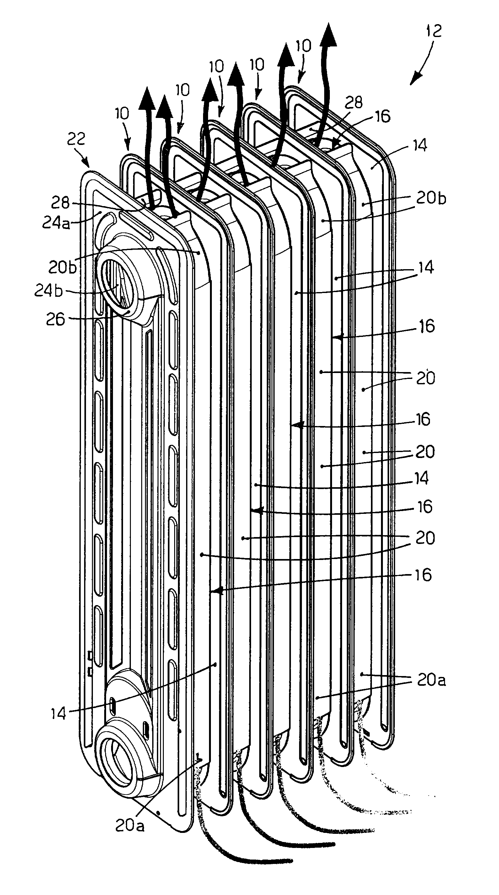
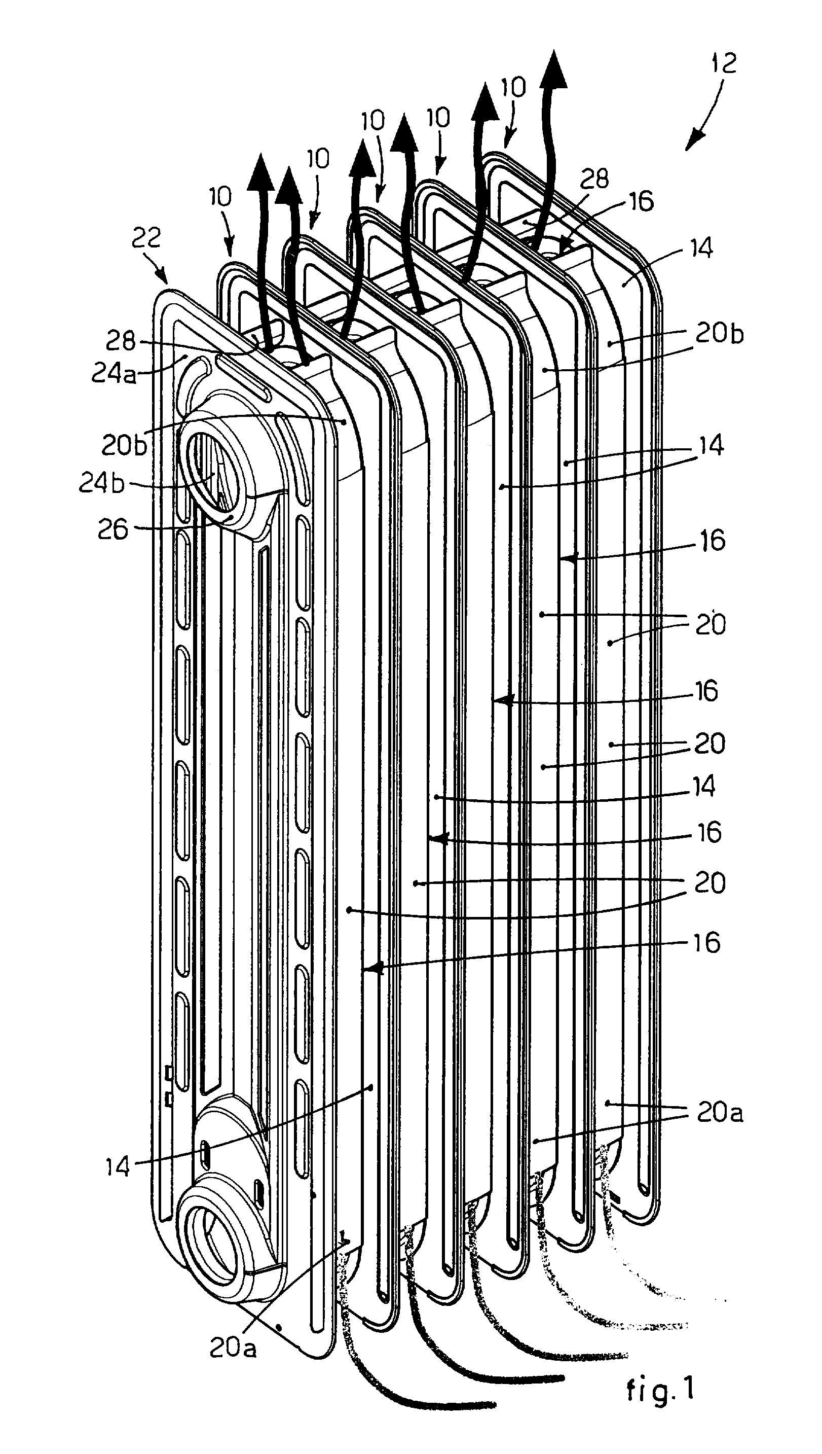
[0027]With reference to FIG. 1, five radiant modules 10 according to the present invention are shown, connected together so as to form a mobile device 12 for heating rooms.

[0028]It is clear, however, that the mobile device 12 can comprise any number whatsoever of radiant modules 10.

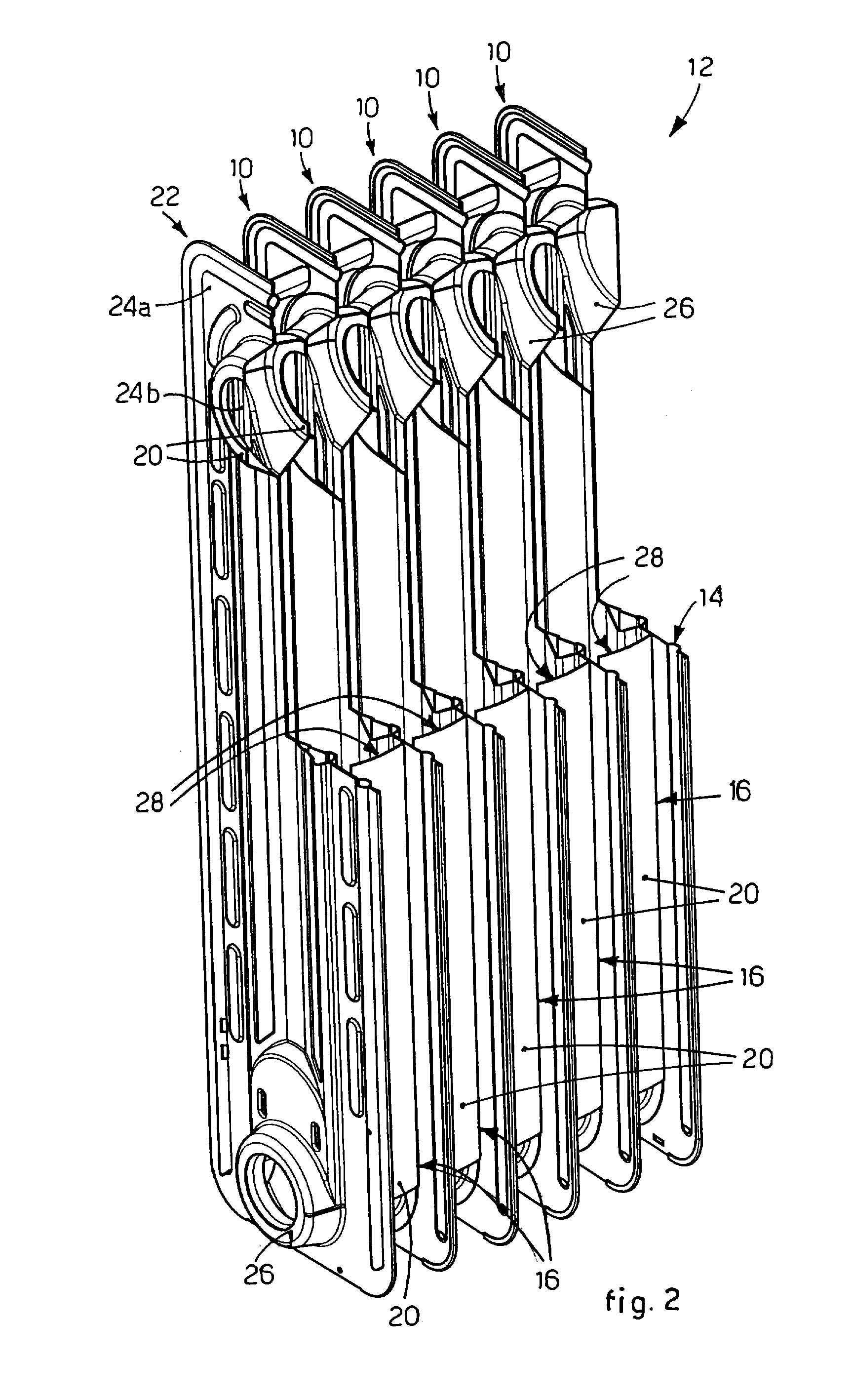
[0029]Each radiant module 10 (FIGS. 1-4) comprises two heat-conductor plates, respectively first 16 and second 14, welded together to define a central portion 18 (FIG. 3), inside which a heat-carrying fluid, heated by means of heating means of a known type and not shown here, is made to flow.

[0030]Moreover, each heat-conductor plate 14 and 16 comprises two collectors 26, disposed at the upper and lower end.

[0031]The first heat-conductor plate 16 also comprises two lateral walls 20 which develop from the central portion 18 substantially orthogonal to a plane on which the second heat-conductor plate 14 lies, and away from the latter.

[0032]The lateral walls 20 are also substantially symmetrical with respect ...


PUM

PropertyMeasurementUnit
distanceaaaaaaaaaa
widthaaaaaaaaaa
electric resistancesaaaaaaaaaa

Abstract

Radiant module and relative method of production, for a heating device for rooms, comprising two heat-conductor plates, respectively first and second, associated with each other to define a central portion inside which a heated heat-carrying fluid flows. The first heat-conductor plate comprises lateral walls which develop from the central portion away from the second heat-conductor plate, to define a channel inside the radiant module which develops and narrows from the lower part of the radiant module towards its upper part and through which a flow of heated air is accelerated and guided.

Description

FIELD OF THE INVENTION[0001]The present invention concerns a radiant module for a device, such as for example a mobile heat radiator, used to heat rooms. In particular, the radiant module comprises two heat-conductor plates associated with each other to define a central portion inside which a heated heat-carrying fluid is made to flow. The present invention also concerns a method to produce said radiant module.BACKGROUND OF THE INVENTION[0002]In the field of heating, heating devices are known, such as for example heat radiators, comprising one or more radiant modules, connected to each other and communicating hydraulically.[0003]Each radiant module comprises two metal plates, normally welded to each other in sealed manner, which define a central portion, more or less extensive with respect to the width of the plate.[0004]The central portions are normally connected hydraulically with each other by means of upper and lower collectors.[0005]A diathermic oil, heated by means of one or m...

Claims


Application Information

Patent Timeline
Patent Type & Authority Applications(United States)
IPC IPC(8): F24H6/00B21D53/02
CPCF28D1/0233Y10T29/4935F28D2021/0035F28D1/0333
Inventor ZANOLIN, SERGIOGRANDIN, FILIPPO
Owner DE LONGHI SPA
Learn More