Energy-saving waste liquid heat exchange treatment device

A heat treatment device and waste liquid technology, which is applied in the field of printing and dyeing machinery, can solve the problems of slow heat exchange, easy scaling, and high price, and achieve the effects of fast heat exchange, avoiding scaling, and low production costs

Inactive Publication Date: 2012-05-30
浙江永洋复合材料科技有限公司
View PDF0 Cites 0 Cited by
  • Summary
  • Abstract
  • Description
  • Claims
  • Application Information

AI Technical Summary

Problems solved by technology

[0003] There are many types of heat exchangers, and all kinds of heat exchangers sold on the market have the defects of high price, slow heat exchange speed, long time consumption, and easy fouling

Method used


Image

  • Energy-saving waste liquid heat exchange treatment device
  • Energy-saving waste liquid heat exchange treatment device
  • Energy-saving waste liquid heat exchange treatment device

Examples


Embodiment

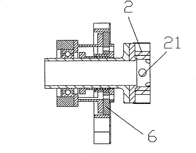
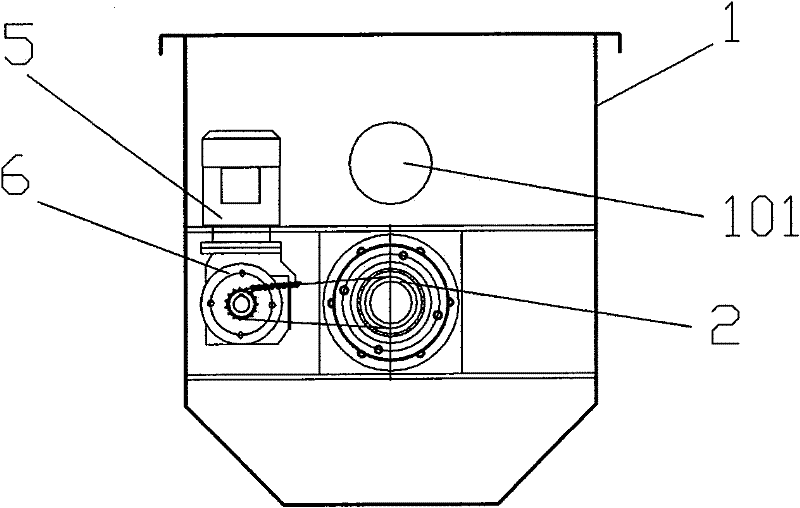
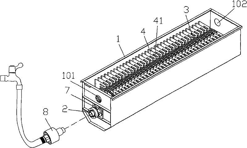
[0016] Example: see Figure 1~4 , a waste liquid energy-saving heat exchange treatment device, a waste liquid inlet 101 and a waste liquid outlet 102 are respectively opened on the two end side plates of the heat exchange box 1, a rotating shaft 2 is arranged in the heat exchange box 1, and a number of shafts are fixed on the rotating shaft 2 Each blade 3, the baffle plate 4 is fixed on the side plates on the two sides of the heat exchange box 1, each blade 3 is placed in the middle of the two baffle plates 4, and several blades 3 are arranged on the rotating shaft 2 in a spiral ascending shape , the motor 5 drives the reducer 6 to rotate, the reducer 6 drives the rotating shaft 2 to rotate, the two end side plates of the heat exchange box 1 are fixed with a bearing seat 7, and the rotating shaft 2 is installed on the bearing seat 7;

[0017] The rotary joint 8 is connected to the end of the rotating shaft 2, and the rotating shaft 2 is formed with a water outlet hole 21 commu...


PUM


Abstract

The invention relates to an energy-saving waste liquid heat exchange treatment device. In the device, a heat exchange box is provided with a waste liquid inlet and a waste liquid outlet; flow baffle plates are fixed on side plates at both sides of the heat exchange box; each blade is arranged between two flow baffle plates, and a plurality of blades are arrayed on a rotating shaft in a spiral forward type; a motor is used for driving a speed reducer to rotate, and the speed reducer drives the rotating shaft to rotate; bearing blocks are fixed on the side plates at both ends of the heat exchange box, and the rotating shaft is arranged on the bearing blocks; a rotating joint is in through connection to the end part of the rotating shaft, and water outlet holes is molded on the rotating shaft and communicated with water inlet holes of the blades; a water inlet tap is welded on the rotating shaft, and two clamping pieces with the same structures are symmetrically welded on the water inlet tap; a partition plate is clamped between the two clamping pieces; water inlet holes are molded on the water inlet tap; and through holes are molded on the partition plate. The device has low production cost, high heat exchange speed and short time consumption; and the design of the rotating structure improves the heat exchange speed, avoids the scaling of waste water in the heat exchange process and can replace heat energy in printing and dyeing waste water into clear water for recycling, thereby saving energy.

Description

Technical field: [0001] The invention relates to the technical field of printing and dyeing machinery, and more specifically relates to a heat energy recovery device in high-temperature printing and dyeing wastewater in the textile printing and dyeing industry. Background technique: [0002] In the printing and dyeing process, most fabrics are dyed under high temperature and high pressure. The dyeing temperature is between 100 and 135°C. After high-temperature dyeing of fabrics, some high-temperature wastewater with a temperature above 95°C will be formed. The factory will treat these dyes. High-temperature wastewater is purified. Before purification, some factories let the heat contained in the high-temperature wastewater naturally cool down to an appropriate temperature before purification. Some factories use liquid heat exchangers to partially recycle the heat. [0003] There are many types of heat exchangers, and all kinds of heat exchangers sold on the market have the d...

Claims


Application Information

Patent Timeline
Patent Type & Authority Patents(China)
IPC IPC(8): F28D1/06F28F13/12
Inventor 陈尧春彭万信谢贤定徐辉州
Owner 浙江永洋复合材料科技有限公司
Why Eureka
Try Eureka