One touch pipe joint

Inactive Publication Date: 2010-12-16
ON IND
View PDF4 Cites 18 Cited by
  • Summary
  • Abstract
  • Description
  • Claims
  • Application Information

AI Technical Summary

Benefits of technology

[0009]According to claim 1, the pipe and the joint are connected such that the blade edges in the central hole of the lock ring bite into the outer circumferential surface of the pipe only with a single motion in which the pipe is pressed into the central hole of the lock ring holder from its tip end until the pipe is stopped by the stopper projection provided in the pipe insertion hole of the joint, thereby effectively preventing the pipe from being pulled out against a force in the direction in which the pile is pulled out. Accordingly, it is possible to improve work efficiency and prevent the pipe from being pulled out. Further, as the blade edges of the locking members in the central hole of the lock ring moves along with the pipe in an inward direction of the joint main body due to a frictional resistance with the outer circumferential surface of the pipe, the central portion is brought into contact with a corner of the opening-side end surface of the joint main body. Accordingly, the outer circumference edge portion is brought into contact with the recess portion in the inner surface of the side wall of the lock ring holder, and biased in a direction opposite to the joint main body. With this, a biased force in the direction opposite to the joint main body is also produced in an entirety of the lock ring holder, and a force that causes the joint main body and the lock ring holder to move away from each other is produced. Accordingly, a high frictional force, which makes the connection between the engaging portion and the engaged portion firm, is produced at the engaging portion between the engaged portion of the joint main body and the engaging portion of the lock ring holder, thereby advantageously preventing the engagement from slackening. Moreover, as the blade edges of the locking members in the central hole of the lock ring move in the inward direction of the joint main body, the front surface of the blade edges press the O-ring toward the cut out portion. This expands a volume of the O-ring in upward and downward directions of the cut out portion. As a result, the outer circumferential surface of the pipe and the O-ring are brought into closer contact with each other, thereby further improving cutoff performance. Moreover, the lock ring can be formed only by integrally processing the tabular elastic metal member in the plated state and configured such that the blade edge is provided, at the side of the central hole, for each of the plurality of locking members defined by the long holes provided radially from the central hole to the outer circumference edge portion. Accordingly, manufacturing is simple and cost can be largely reduced, in comparison with the conventional technique in which a regulation piece is provided for an inner circumferential surface of a ring in a disc spring shape. Further,

Problems solved by technology

However, the joint main body and the cap member are coupled by threading according to this configuration, and t

Method used


Image

  • One touch pipe joint
  • One touch pipe joint
  • One touch pipe joint

Examples


Example

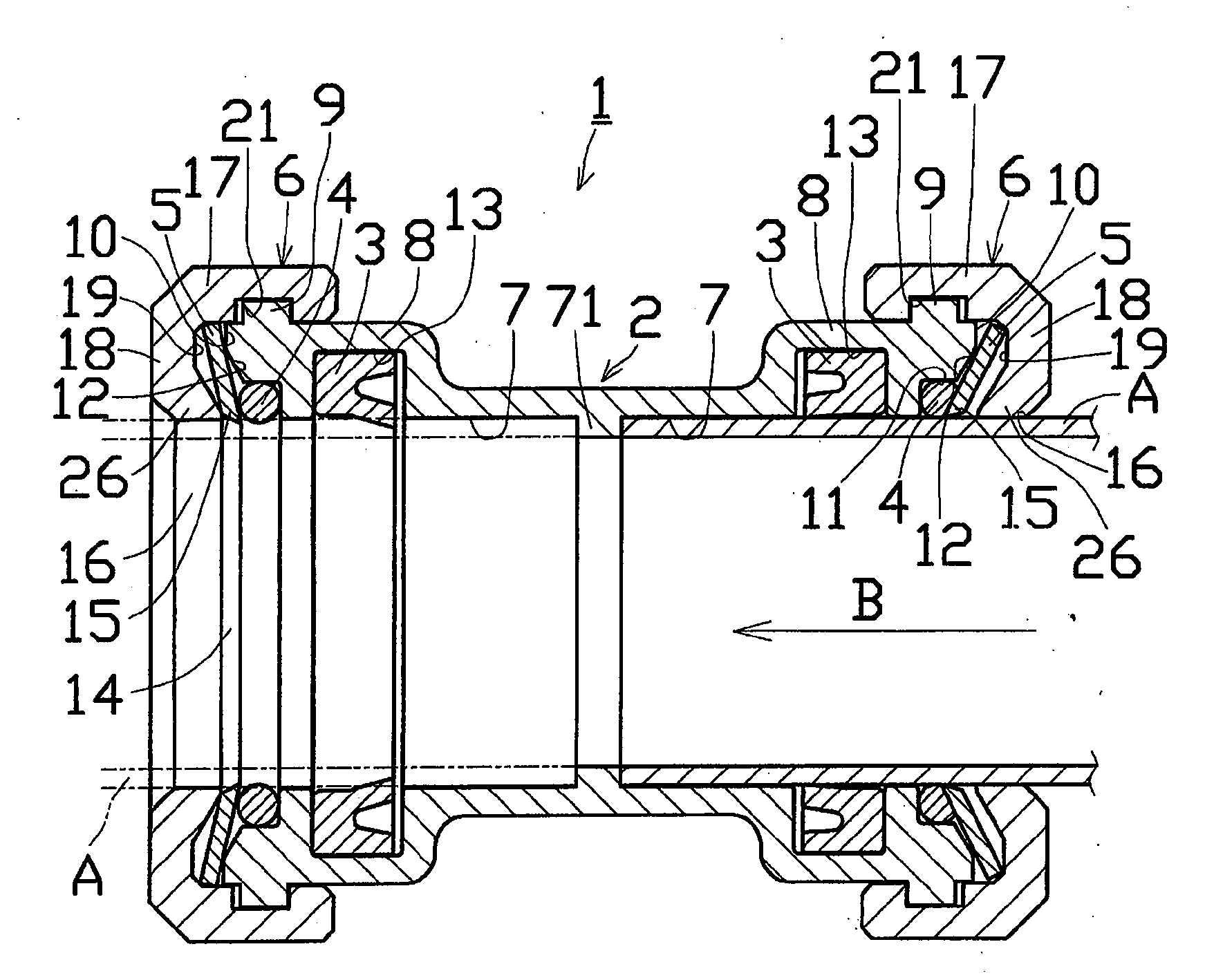
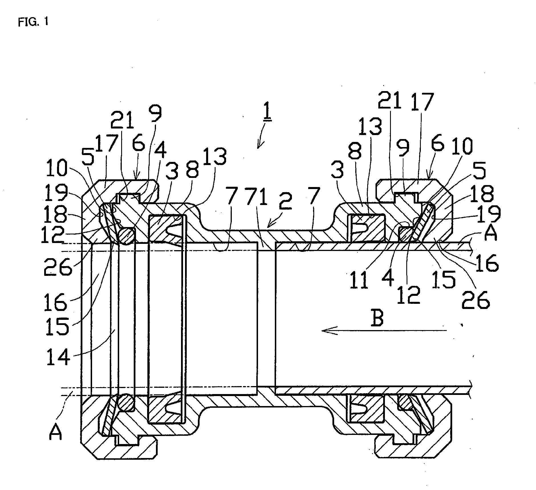
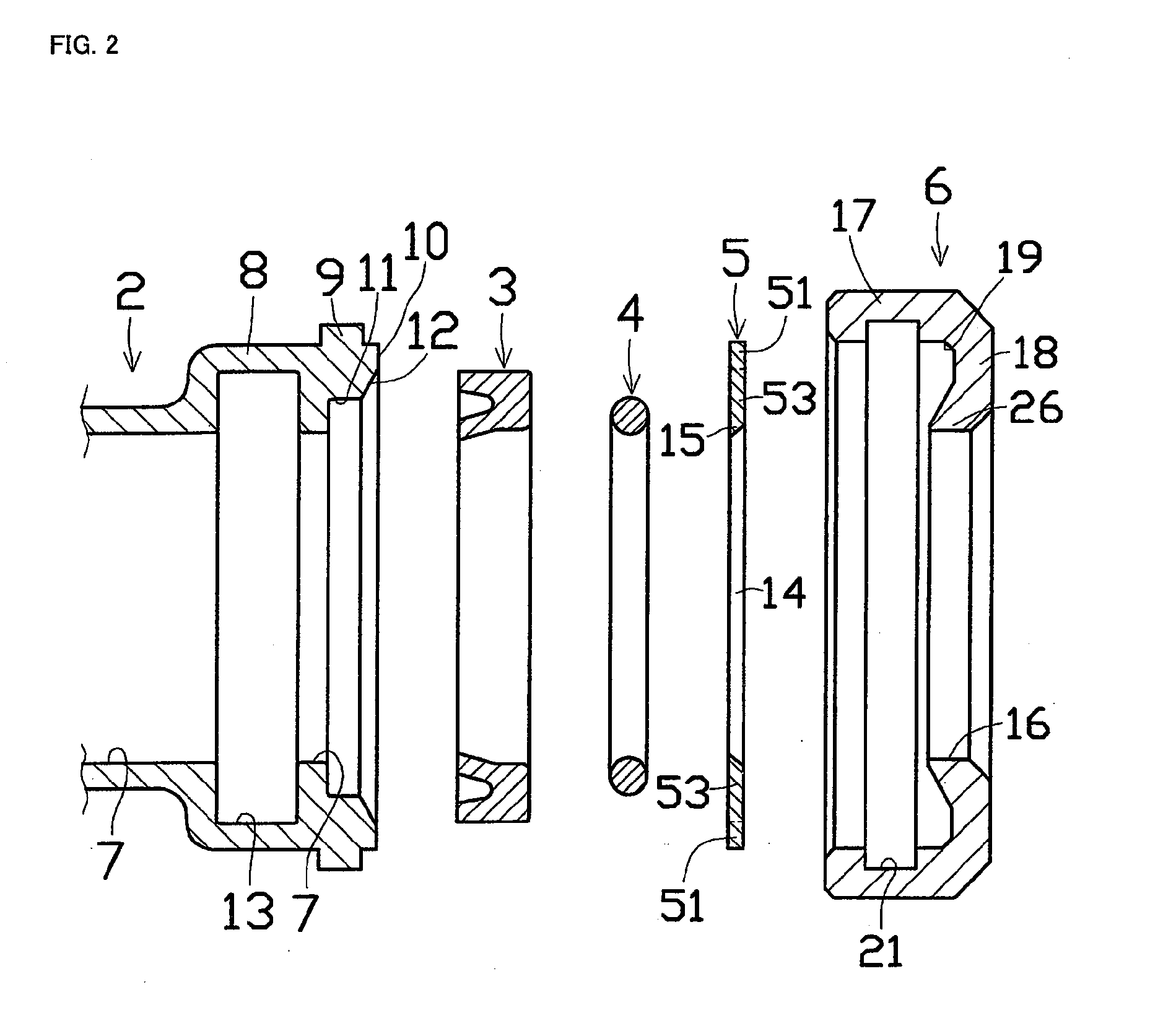
[0014]As shown in FIG. 1 to FIG. 3, a one touch pipe joint 1 of a first embodiment according to the present invention is provided with a joint main body 2, a rubber packing 3, an O-ring 4, a lock ring 5, and a lock ring holder 6 as major components.

[0015]An outer circumference of an opening-side end portion of a pipe insertion hole 7 at a center of joint main body 2 constitutes an expanded portion 8, and a plurality of engagement projections 9 that engage with lock ring holder 6 are provided at a predetermined interval along an outer circumferential surface of expanded portion 8. Further, a cut out portion 11 in which O-ring 4 is contained is provided for an inner circumference of an opening-side end surface 10 so as to open to pipe insertion hole 7 and opening-side end surface 10, and a slanted surface 12 that extends from cut out portion 11 to opening-side end surface 10 is provided as needed. Slanted surface 12 is provided only to effectively secure a space for containing lock ri...

Example

[0025]A second embodiment according to the present invention is now described with reference to FIG. 4 to FIG. 6. The second embodiment is different from the first embodiment in that the engagement between joint main body 2 and lock ring holder 6. Accordingly, the description focuses on this part and the like components are represented by the like numerals and not explained.

[0026]The outer circumference of the opening-side end portion of pipe insertion hole 7 at the center of joint main body 2 constitutes a reduction portion 22, and an external thread 23 is provided around an outer circumference thereof. Further, the inner circumferential surface of retaining annular portion 17 of lock ring holder 6 through which an opening end portion of reduction portion 22 is inserted is provided with an internal thread 24 that can be threaded with external thread 23. Further, packing fitting hole 13 is provided so as to be laterally long with a central portion being deep, within which a large O-...


PUM


Abstract

[Problems] A one-touch joint for piping has an advantage of one-touch connection between the joint and piping but has a problem that the connection between the piping and a joint body easily becomes loose.
[Means for Solving Problems] A one-touch joint (1) of the invention includes a joint body (2) having an engagement receiving section (9, 23) on the outer periphery of an opening-side end section of the joint body, a lock ring holder (6) having an engaging ring section (17) having, formed on its inner side, an engaging section (20, 21, 24) engageable with and disengageable from the engagement receiving section (9, 23), a planar lock ring (5) placed between a recess (19) formed in an inner surface of the lock ring holder (6) and an opening-side inner surface (10) of the joint body (2) and having, in its center hole (14), a cutting edge (15) of an engaging section (53), an O-ring (4) received in a cutout section (11) of the joint body (2), rubber packing (3) fitted in a packing insertion hole (13) located closer to the inner side of the joint than the cutout section (11), and a stop projection (71) projecting in a piping insertion hole (7) of the joint body (2).

Description

TECHNICAL FIELD[0001]The present invention relates to a one touch pipe joint which can be firmly coupled to a pipe with a simple operation.BACKGROUND ART[0002]Coupling pipes such as water pipes or raceways provided within rooms in a building to a joint must be carried out quickly and firmly, because there are a lot of such operations depending on the scale of the building and the number of rooms within the building. One example of joints according to inventions that address such a demand is a one touch joint disclosed in Patent Document 1. The joint according to this background art is configured such that, when connecting a pipe to a joint main body, an external thread provided for the joint main body is threaded with an internal thread provided for a cap member so that a lock ring and such in a disc spring shape provided with a regulation piece at an inner circumferential surface of the ring is fixed. Then, the pipe is inserted into the joint main body through the cap member, and t...

Claims


Application Information

Patent Timeline
IPC IPC(8): F16L25/12
CPCF16L37/091F16L37/10F16L37/113
Inventor OHARA, KOJITSUNETO, KAZUHARU
Owner ON IND
Why Eureka
Try Eureka