Wide color gamut projector

Active Publication Date: 2010-12-16
INTERDIGITAL CE PATENT HLDG
View PDF20 Cites 24 Cited by
  • Summary
  • Abstract
  • Description
  • Claims
  • Application Information

AI Technical Summary

Problems solved by technology

One problem with current systems for providing 3D images is that the projectionist must attach and configure an external special device to the standard projector, a costly and time consuming requirement which also leads to technical failure.
In addition, having such a device attached to the projector parallel to the projection lens surface introduces a risk that lig

Method used


Image

  • Wide color gamut projector
  • Wide color gamut projector
  • Wide color gamut projector

Examples


Embodiment Construction

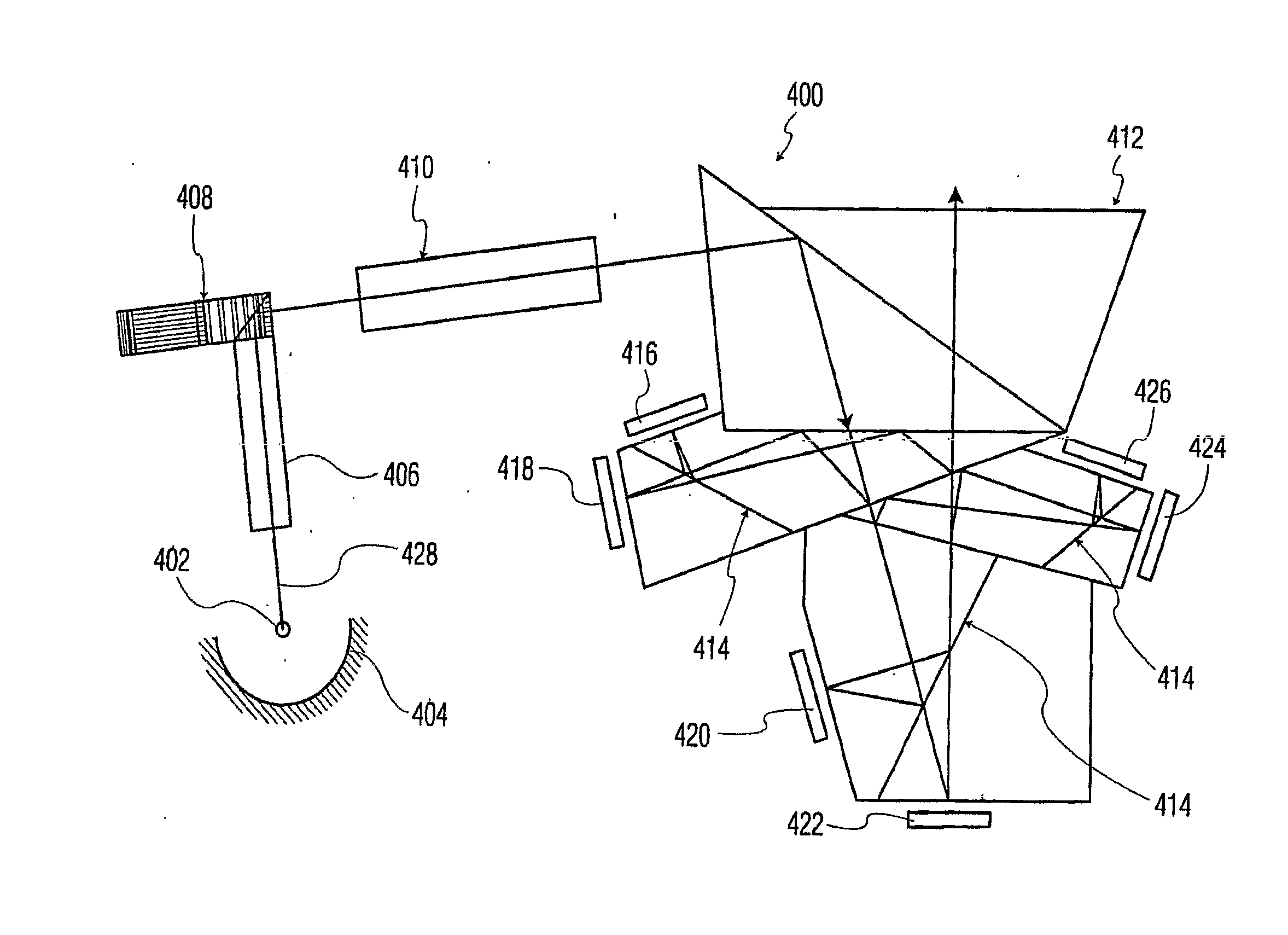
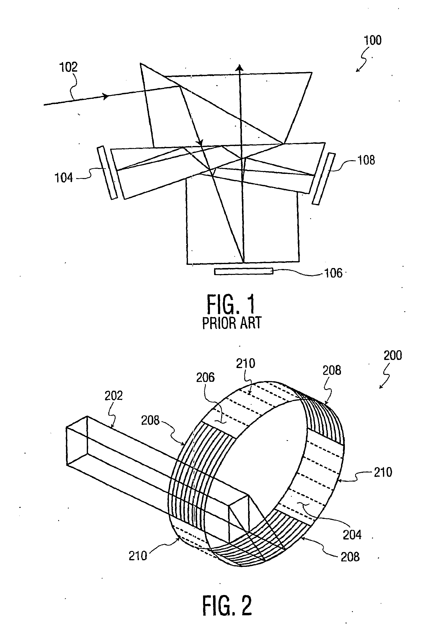
[0010]Referring now to FIG. 2 in the drawings, a polarizing drum (or otherwise called a polarization hollow cylinder) according to a first embodiment of the present invention is illustrated. Polarizing drum 200 is a rotatable drum-like structure formed of translucent materials. Drum 200 is shown as a flat band of material located in close proximity to a directional light transmission device (or light pipe) 202 for passing light through drum 200 by directing light generally orthogonal to an interior surface 204 of the drum 200 such that light passes through the translucent material and exits the drum 200 through an exterior surface 206 of the drum 200 (through a wall of the drum). As shown, the drum is divided into radially alternating P-polarization sections 208 (or clockwise circular polarization sections) and S-polarization sections 210 (or counter-clockwise circular polarization sections). In operation, a 2D image may be converted to a 3D image by transmitting the 2D image throug...


PUM


Abstract

A wide color gamut projector having a plurality of dichroic prisms configured to split a light beam into six primary color components and direct each of the six primary color components to separate digital micromirror devices is disclosed. The projector further comprises a translucent rotatable drum having different polarization sections, wherein the light beam is capable of being passed orthogonally through a wall of the drum.

Description

FIELD OF THE INVENTION[0001]The invention relates generally to the projection of images. More specifically, the invention relates to the projection of images with a wide color gamut.BACKGROUND OF THE INVENTION[0002]It is well known that a projected image may be enhanced with an appearance of depth by converting the projected image into a so-called 3D image. This is generally accomplished by optically polarizing the images which are to be viewed by a viewer's left eye differently than the images which are to be viewed by a viewer's right eye. The 3D effect is perceived by the viewer when the viewer views the polarized images through the use of polarized filter lenses, commonly configured as ‘3D viewing glasses’ with a polarized filter for use with the left eye of the viewer and a differently polarized filter for use with the right eye of the viewer. When the 3D viewing glasses are used to view the 3D images, the left eye of the viewer sees only the light polarized appropriately for p...

Claims


Application Information

Patent Timeline
IPC IPC(8): G02B27/14G03B21/14G02B27/28G02B30/25
CPCG02B5/3025G02B26/00G02B27/1026G02B27/145G02B27/26H04N13/365H04N9/3167H04N13/341H04N13/324H04N13/363H04N9/3105G02B30/25G02B27/14
Inventor YOON, YOUNGSHIK
Owner INTERDIGITAL CE PATENT HLDG
Why Eureka
Try Eureka