Anti-gravity thermosyphon heat exchanger and a power module

a heat exchanger and antigravity technology, applied in the direction of cooling/ventilation/heating modification, semiconductor devices, lighting and heating apparatus, etc., can solve the problems of time and cost, inability to easily re-mount the power electronic module, and a risk of damaging the expensive power electronic devi

Inactive Publication Date: 2010-12-16
ABB RES LTD
View PDF15 Cites 54 Cited by
  • Summary
  • Abstract
  • Description
  • Claims
  • Application Information

AI Technical Summary

Benefits of technology

[0005]A thermosyphon heat exchanger is disclosed which includes at least one set of linear conduit elements. At least one heat exchange plate is mounted in a heat receiving region of the linear conduit elements. Longitudinal axes of the linear conduit elements are arranged in a first direction running through or being parallel to a plane defined by the heat exchange plate. The at least one set of linear conduit elements extends beyond the heat receiving region on a first side and on an opposing second side in the first direction such that an extension of the at least one set of linear conduit elements on one of the first and second sides of the heat receiving region constitutes a condensing region for condensing a refrigerant vaporized in the heat receiving region in one of the first or second side that is arranged higher than the extension on the other side with respect to the direction of gravity in an operating state of the thermosyphon heat exchanger. The extension of the other side constitutes a liquid reservoir.
[0006]A power module is disclosed which includes at least one heat emitting device and at least one ther

Problems solved by technology

In the former, the re-mounting process can be time and cost intensive and contains a risk of damaging the expensive power electronic devices.
Sometimes the power electronic modules are fixed to the thermosyphon heat exchanger so that an easy re-mounting of the power electronic module is not possible.
In the latter, anti-gravity thermosyphon heat exchangers are very expensive, because of the use of special coatings in the conduit elements to move the refrigerant by capillary forces instead of gravity

Method used


Image

  • Anti-gravity thermosyphon heat exchanger and a power module
  • Anti-gravity thermosyphon heat exchanger and a power module
  • Anti-gravity thermosyphon heat exchanger and a power module

Examples


first embodiment

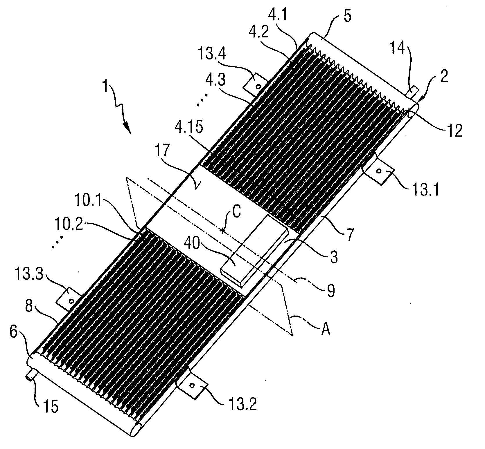
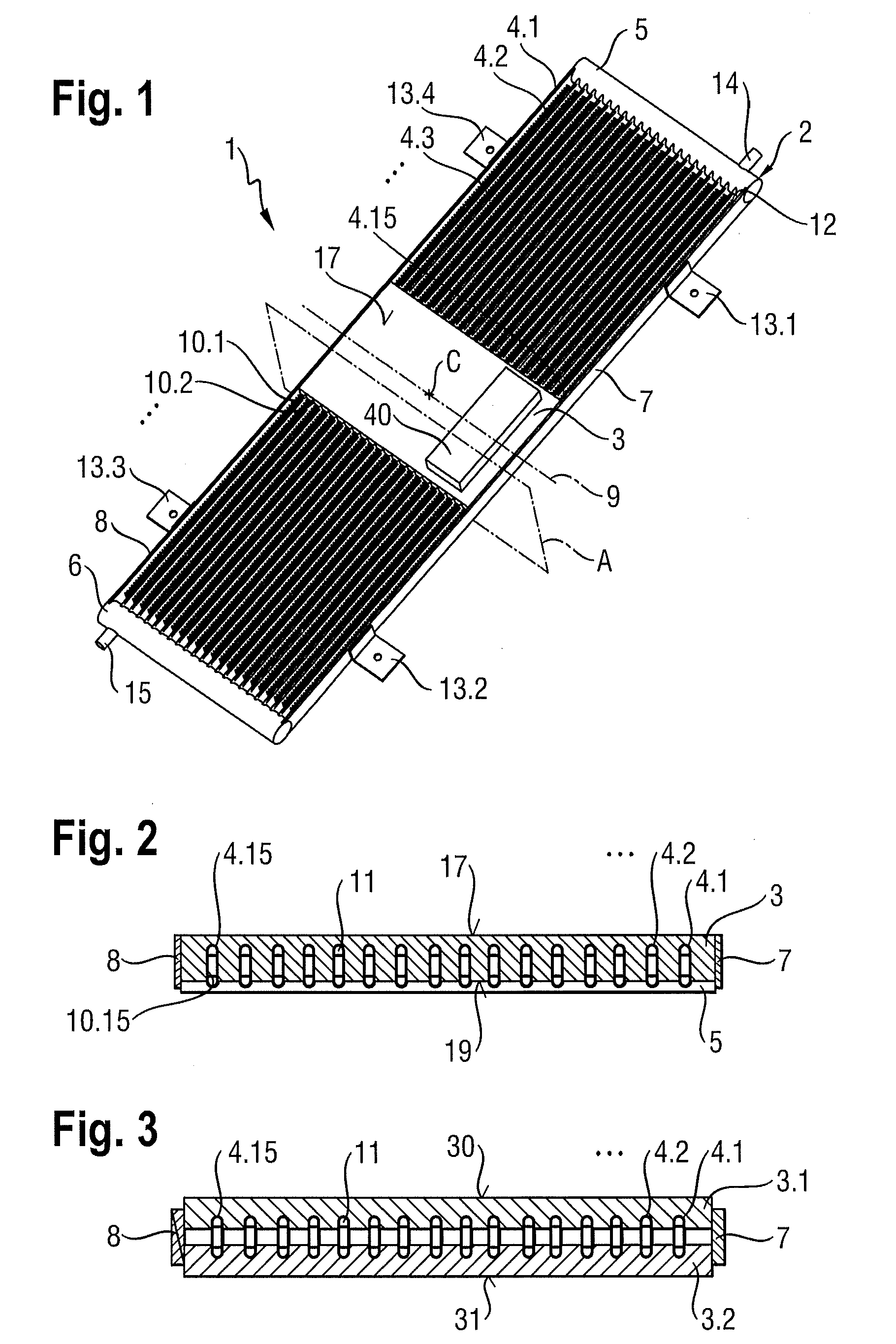
[0045]FIG. 3 shows an alternative embodiment of the first embodiment with respect to the heat exchange plate 3. In the alternative embodiment on two sides of the set 2 of multiport extruded tubes 4.1 to 4.15 with respect to the plane of the multiport extruded tubes 4.1 to 4.15, a first and a second heat exchange plate 3.1 and 3.2 are mounted on the multiport extruded tubes 4.1 to 4.15. Each of the first and second heat exchange plate 3.1 and 3.2 can have on one side grooves which have a profile like the profile of the multiport extruded tubes 4.1 to 4.15 of the set 2. The first heat exchange plate 3.1 can be bonded with the grooves to a first side of the set 2 of multiport extruded tubes 4.1 to 4.15 with respect to the plane of the set 2 such that all multiport extruded tubes 4.1 to 4.15 enter in the corresponding grooves of the first heat exchange plate 3.1. Each multiport extruded tube 4.1 to 4.15 enters at maximum half the dimension of the multiport extruded tube 4.1 to 4.15 in t...

second embodiment

[0051]FIGS. 8 and 9 illustrate an exemplary thermosyphon heat exchanger 20 according to the disclosure. The exemplary thermosyphon heat exchanger 20 includes a first set 22 of multiport extruded tubes 23.1 to 23.10 and a second set 23 of multiport extruded tubes 24.1 to 24.10. Each set 21 and 22 can be designed as the set 2 of the first exemplary embodiment of the disclosure including manifolds, fins, refrigerant connections, fixing devices, etc. The multiport extruded tubes 23.1 to 23.10 or 24.1 to 24.10 within one set 21 or 22 are arranged with their longitudinal axes in parallel. The multiport extruded tubes 23.1 to 23.10 of the first set 21 can be arranged in a first plane and their longitudinal axes are a ligand in a first direction 25. Thus, the first set 21 has a longitudinal axis 27 aligned in the same direction as the longitudinal axis of the multiport extruded tubes 23.1 to 23.10. The multiport extruded tubes 24.1 to 24.10 of the second set 22 can be arranged in a second p...


PUM


Abstract

A thermosyphon heat exchanger according to the disclosure includes a set of linear conduit elements and a heat exchange plate mounted in a heat receiving region on the conduit elements. The longitudinal axes of the conduit elements extend in a first direction in a plane defined by the flat side of the heat exchange plate. The conduit elements project above the heat receiving region in the first direction on a first side and an opposing second side such that the extension of the conduit elements on each side of the heat exchange region is suitable for constituting a condensing region for condensing a refrigerant vaporized in the heat receiving region if the first direction is arranged vertically.

Description

RELATED APPLICATIONS[0001]This application claims priority under 35 U.S.C. §119 to European Patent Application No. 09162370.2 filed in Europe on Jun. 10, 2009, the entire content of which is hereby incorporated by reference in its entirety.FIELD[0002]The disclosure relates to an anti-gravity thermosyphon heat exchanger and a power module including an anti-gravity thermosyphon heat exchanger.BACKGROUND INFORMATION[0003]Known thermosyphon heat exchangers can include a heat receiving region at a bottom side of the thermosyphon heat exchanger for vaporizing a refrigerant and a condensing region at an upper side for condensing the vaporized refrigerant ascended to the condensing region. Some power electronic devices mounted on the thermosyphon heat exchanger can be mounted upside-down, for example in traction applications. Thus, either the power electronic device has to be re-mounted upside-down on the thermosyphon or cost-intensive anti-gravity thermosyphon heat exchanger have to be use...

Claims


Application Information

Patent Timeline
IPC IPC(8): H05K7/20F28D15/02
CPCF28D15/0233F28D15/0266F28D15/0283H01L23/427F28D15/0275H01L2924/0002H01L2924/00
Inventor AGOSTINI, BRUNO
Owner ABB RES LTD
Why Eureka
Try Eureka