Curved light guiding illuminator

a technology of guiding illuminator and light guide plate, which is applied in the direction of lighting and heating apparatus, instruments, semiconductor devices for light sources, etc., can solve the problem of inability to improve the illumination range, and achieve the effect of widening the irradiation area

Inactive Publication Date: 2010-12-16
LITEK OPTO ELECTRONICS
View PDF5 Cites 35 Cited by
  • Summary
  • Abstract
  • Description
  • Claims
  • Application Information

AI Technical Summary

Benefits of technology

[0010]The primary object of the present invention is to provide a curved light guiding illuminator which is primarily assembled by a curved light guide plate, a diffuser plate and a reflector, wherein at least one end edge of the curved light guide plate is provided with plural light emitting elements, one side of the curved light guide plate is formed with a rough surface to change a light path, and an exterior side of the curved light guide plate is formed with plural V-shape grooves. Hence, when a reflection layer which covers on an inner surface of the curved light guide plate is impinged by light from the light emitting elements, the light path can be changed by a rough reflection region, allowing the reflected light to emit out through a surface of the reflection region, so as to provide a wider area of irradiation. Furthermore, by using the V-shape grooves, light is reflected onto the diffuser plate on the exterior side of the curved light guide plate, which increases a diffusion angle of the light after being reflected, so as to provide an even wider area of irradiation.

Problems solved by technology

However, upon using the aforementioned direct-type light guide plate, following issues and shortcomings actually exist for improvement:1. A number of the light emitting diodes 14 for this kind of structure will affect the entire luminance.2. As this illumination structure is a direct-type illuminator, if the light emitting diodes 14 are not placed symmetrically or uniformly, then non-uniform light will be resulted, wherein a user will see plural LED (Light Emitting Diode) light dots with lower brightness between the LEDs, thereby forming non-uniform light.3. As the light emitting diodes 14 emit direct-type light, an area on which light irradiates is smaller relatively, and therefore, a range of illumination cannot be improved.

Method used


Image

  • Curved light guiding illuminator
  • Curved light guiding illuminator
  • Curved light guiding illuminator

Examples


Embodiment Construction

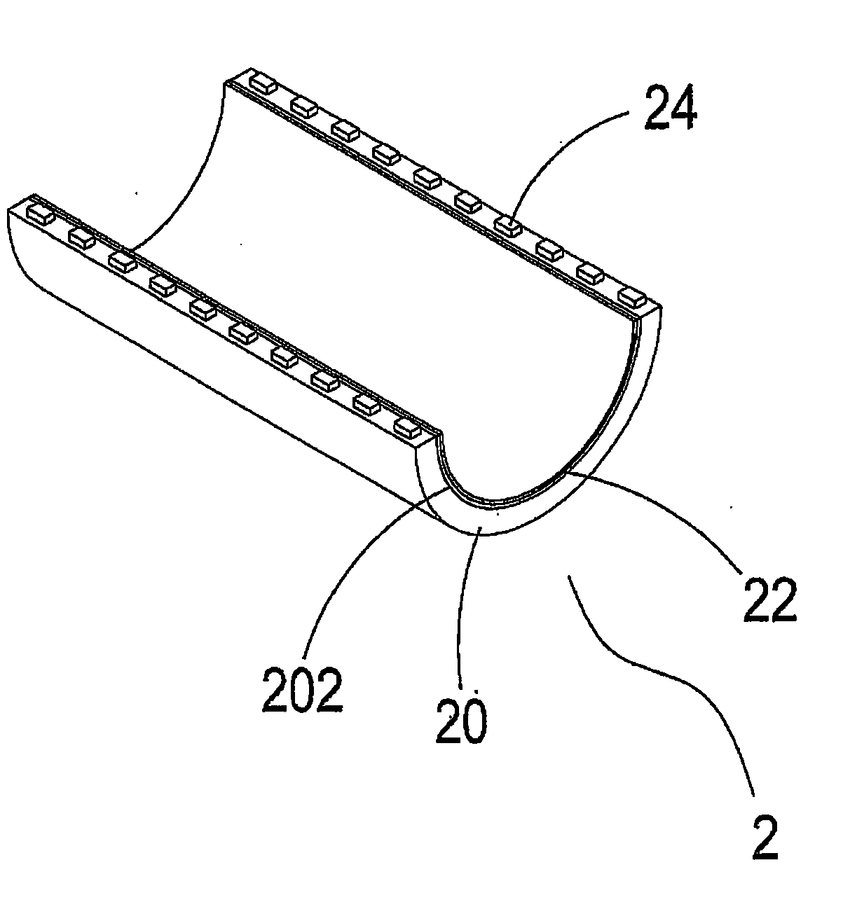
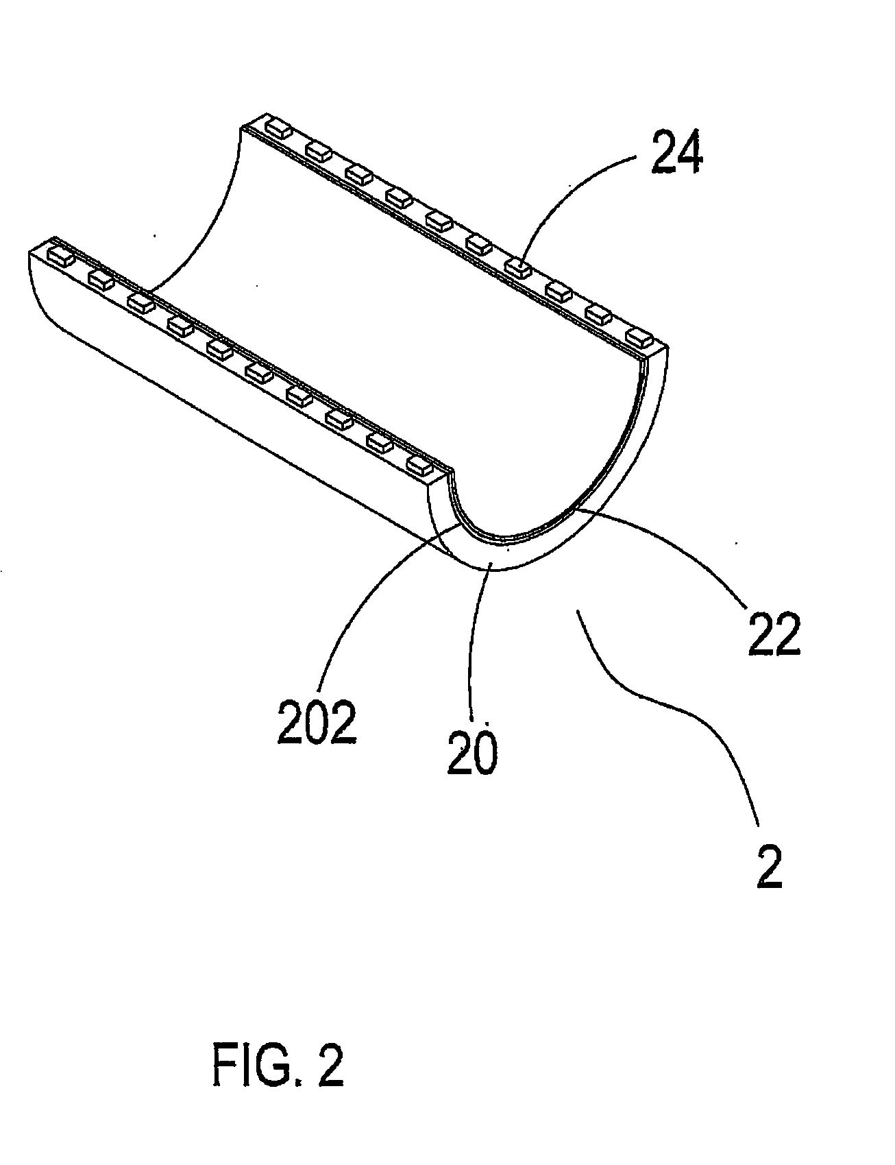
[0024]Referring to FIGS. 2, 2A and 3, it shows a three-dimensional schematic view of a curved light guide plate, two end edges of which are provided with plural LEDs, a three-dimensional exploded view of FIG. 2 and a schematic view of a light path of the structure in FIG. 2, according to the present invention. As shown in the drawings, the present invention is a curved light guiding illuminator. This light guiding structure 2 comprises primarily a curved light guide plate 20 (e.g., transparent or semi-transparent) and a reflection layer 22 (e.g., a reflector), wherein two end edges of the curved light guide plate 20 are provided with plural light emitting elements 24 (LEDs) and one side of the curved light guide plate 20 is formed with a reflection region 202 (such as a rough surface, a sunk spot or mesh region) to change a light path. In addition, the reflection region 202, which is on an inner surface of the curved light guide plate 20, is covered with the reflection layer 22 to r...


PUM


Abstract

A curved light guiding illuminator includes primarily a curved light guide plate, a diffuser plate and a reflector. At least one edge of the curved light guide plate has plural light emitting elements, and one side of the curved light guide plate is a rough surface to change a light path. Therefore, the path of light generated by the light emitting elements at one edge of the light guide plate is changed by being reflected through the rough surface inside the light guide plate, and a wider area of irradiation is provided.

Description

BACKGROUND OF THE INVENTION[0001]a) Field of the Invention[0002]The present invention relates to a light guide plate, and more particularly to a curved light guiding illuminator which can largely increase entire illumination brightness and range.[0003]b) Description of the Prior Art[0004]Referring to FIG. 1, it shows a conventional direct-type light guide plate. As shown in the drawing, this illumination device 1 is constituted by a diffuser plate 10, a circuit board 12 and light emitting diodes 14, wherein the circuit board 12 is provided with the plural light emitting diodes 14, and the diffuser plate 10 is installed at a location facing toward the light emitting diodes 14. Hence, light which emits from the light emitting diodes 14 will directly irradiate on the diffuser plate 10 and will be guided outside to achieve an illuminating effect. If brightness needs to be increased, then it needs to replace with another circuit board having more light emitting diodes 14 that an effect o...

Claims


Application Information

Patent Timeline
Patent Type & Authority Applications(United States)
IPC IPC(8): F21V1/00
CPCF21V13/04G02B6/0036G02B6/0038G02B6/0045G02B6/0051G02B6/0055G02B6/0068F21Y2103/10F21Y2115/10
Inventor CHEN, SHIH-CHOUCHEN, ZHI-ZHONGLAN, HUNG-CHANGHSU, CHING-TAI
Owner LITEK OPTO ELECTRONICS
Why Eureka
Try Eureka