Jet pump riser brace clamp

a technology of riser braces and pump springs, which is applied in the direction of nuclear reactors, nuclear elements, greenhouse gas reduction, etc., can solve the problems of repeat failure, longer installation time of apparatuses, methods, etc., and expose operators to longer periods of radioactivity

Inactive Publication Date: 2010-12-16
GE HITACHI NUCLEAR ENERGY AMERICAS
View PDF3 Cites 11 Cited by
  • Summary
  • Abstract
  • Description
  • Claims
  • Application Information

AI Technical Summary

Benefits of technology

[0014]In accordance with an embodiment of the present invention, an apparatus for integrating a riser brace with an inlet riser of a jet pump assembly, wherein the inlet riser comprises a central longitudinal axis and the riser brace comprises first and second side members extending from a yoke which engages a portion of the inlet riser, and wherein the first and second side members extend transversely to the central longitudinal axis on opposite sides of the inlet riser, the apparatus comprising: a) a saddle for securing a position an inlet riser of

Problems solved by technology

Currently known solutions require re-welding or integrate with existing welds, which may lead to a repeat failure.
These apparatuses, methods, and systems also generally require longer in

Method used


Image

  • Jet pump riser brace clamp
  • Jet pump riser brace clamp
  • Jet pump riser brace clamp

Examples


Embodiment Construction

[0022]Certain terminology may be used herein for convenience only and is not to be taken as a limitation on the invention. For example, words such as “upper”, “lower”, “left”, “front”, “right”, “horizontal”, “vertical”, “upstream”, “downstream”, “fore”, and “aft” merely describe the configuration shown in the FIGS. Indeed, the components may be oriented in any direction and the terminology, therefore, should be understood as encompassing such variations unless specified otherwise.

[0023]As used herein, an element or step recited in the singular and preceded with “a” or “an” should be understood as not excluding plural elements or steps, unless such exclusion is explicitly recited. Furthermore, references to “an embodiment” of the present invention are not intended to exclude additional embodiments incorporating the recited features.

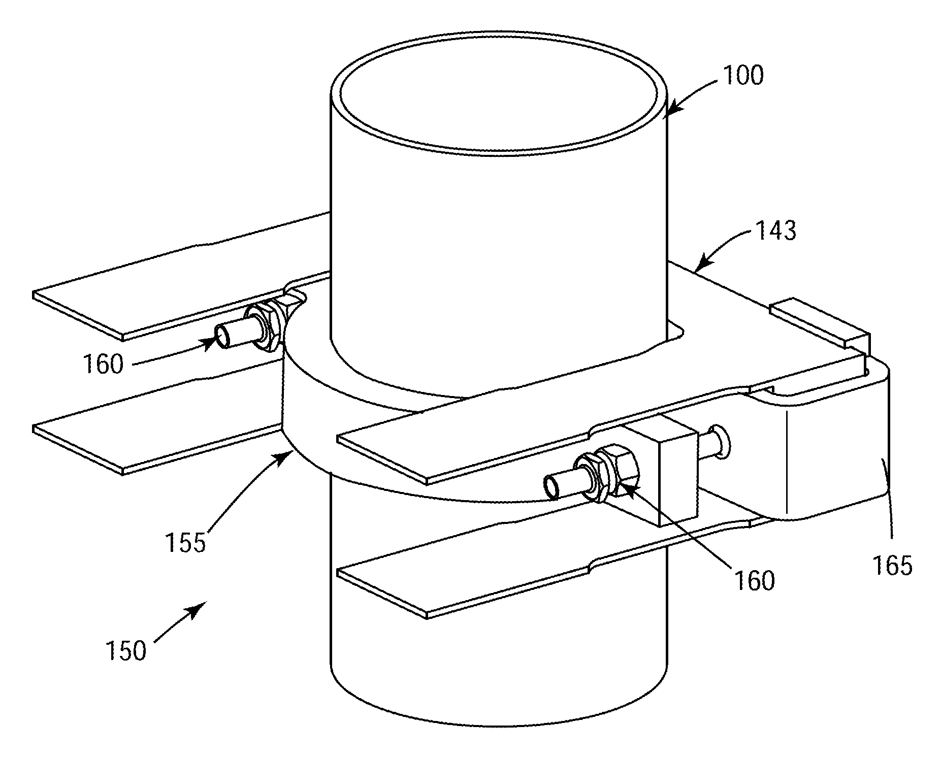
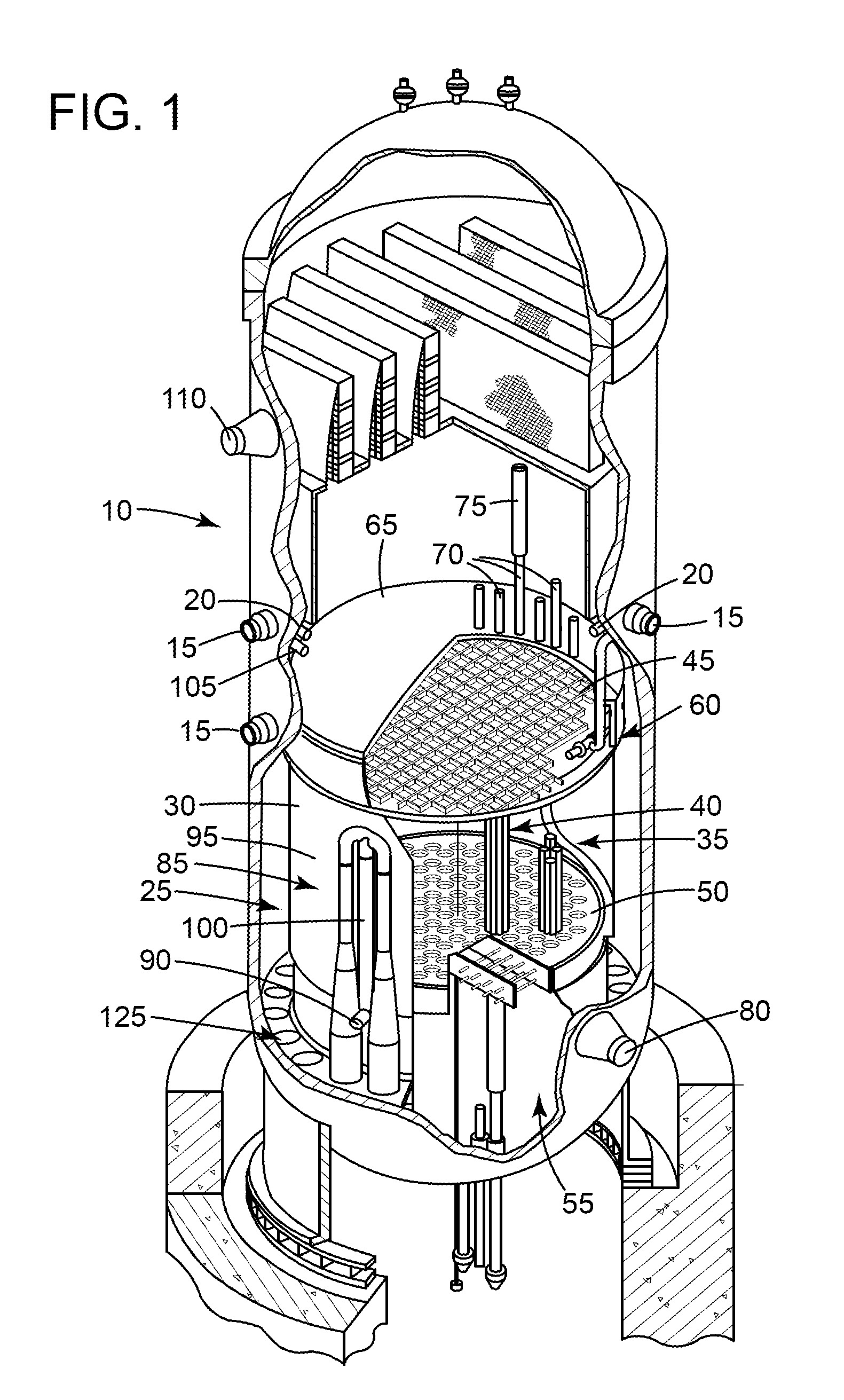
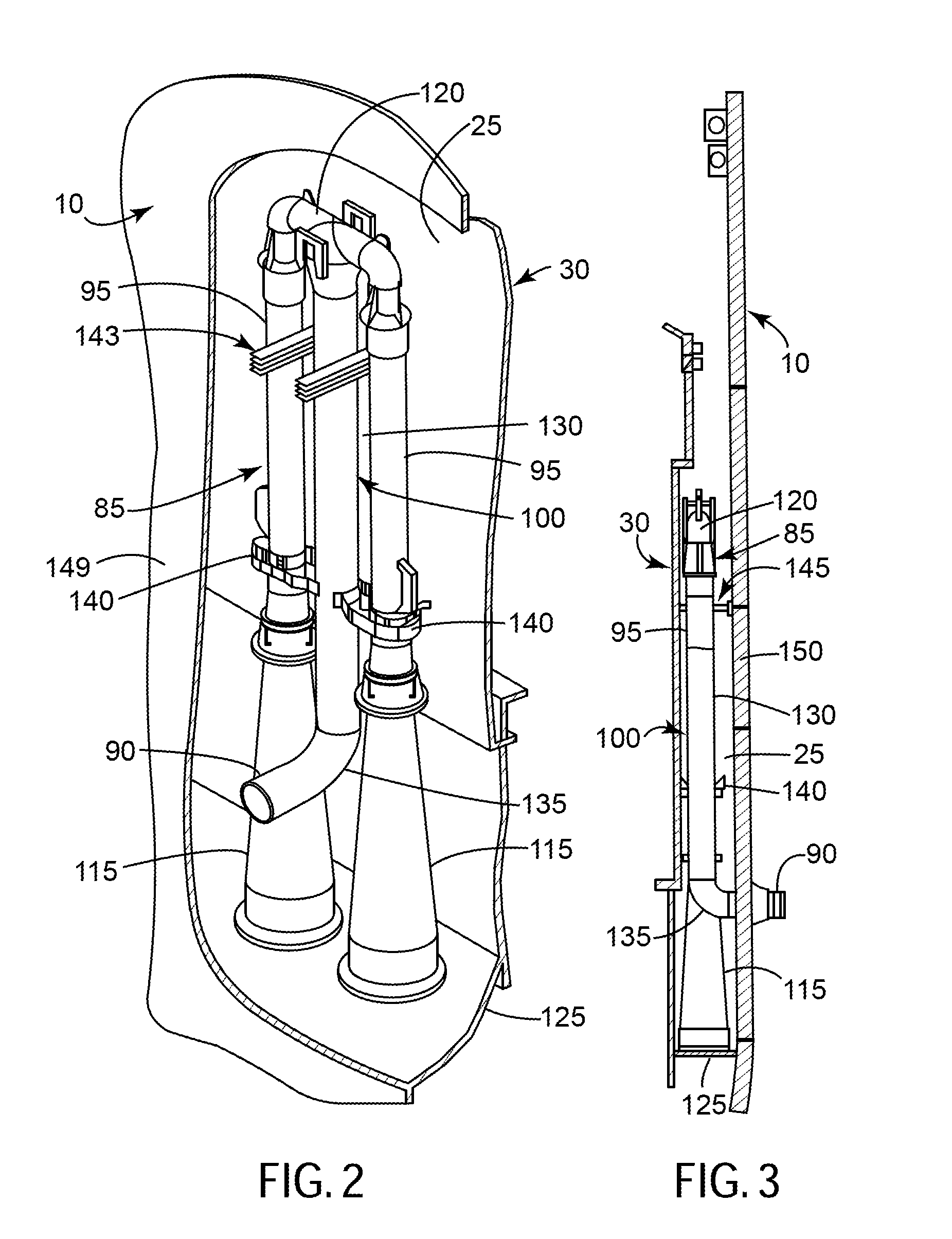
[0024]The following discussion focuses on an embodiment of the present invention integrated with the jet pump assemblies 85 of the RPV 10. Other embodimen...


PUM


Abstract

An embodiment of the present invention takes the form of an apparatus or system that may reduce the level of vibration experienced by an inlet riser or other similar object within a reactor pressure vessel. An embodiment of the present invention may eliminate the need for welding the riser brace to the inlet riser. An embodiment of the present invention provides at least one riser brace clamp that generally clamps the riser brace to the inlet riser. After installation, the riser brace clamp may lower the amplitude of, and/or change the frequency of, the vibration experienced by the inlet riser.

Description

BACKGROUND OF THE INVENTION[0001]The present invention relates generally to the welds between that connect some components of a nuclear reactor pressure vessel; and more particularly to an apparatus and system for replacing the welds between components.[0002]A non-limiting example of a nuclear reactor, a conventional boiling water reactor (BWR) is shown in FIGS. 1-3. A typical BWR includes: a reactor pressure vessel (RPV) 10, a core shroud 30 disposed within the RPV 10, and a nuclear fuel core 35. The core shroud 30 is a cylinder that surrounds the nuclear fuel core 35, which includes a plurality of fuel bundle assemblies 40 disposed within the core shroud 30. A top guide 45 and a core plate 50 supports each of the fuel bundle assemblies 40.[0003]An annular region between the core shroud 30 and the RPV 10 is considered the downcorner annulus 25. Coolant water flows through the downcorner annulus 25 and into the core lower plenum 55. Feedwater enters the RPV 10 via a feedwater inlet ...

Claims


Application Information

Patent Timeline
IPC IPC(8): G21C19/00G21C9/00
CPCF04F5/54F16L3/1091G21C13/032G21C15/25G21C17/017G21C19/40Y02E30/40Y02E30/30
Inventor LENTNER, BRUCE J.DEFILIPPIS, MICHAEL S.
Owner GE HITACHI NUCLEAR ENERGY AMERICAS
Why Eureka
Try Eureka