
Stepped-edge and side-support members, assemblies, systems, and related methods, particularly for bedding and seating

Inactive Publication Date: 2010-12-23
NOMACO
View PDF99 Cites 62 Cited by
  • Summary
  • Abstract
  • Description
  • Claims
  • Application Information

AI Technical Summary

Benefits of technology

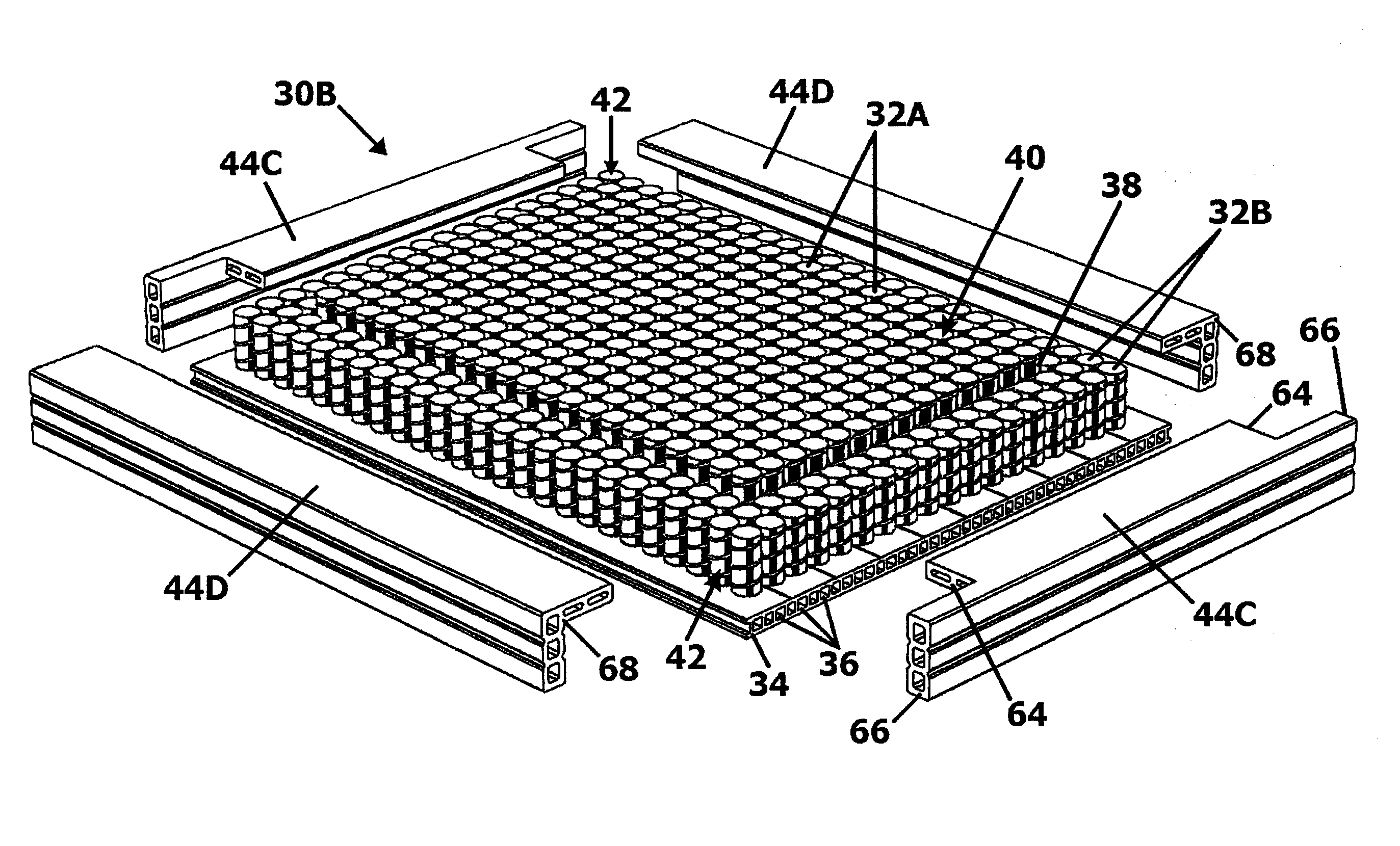
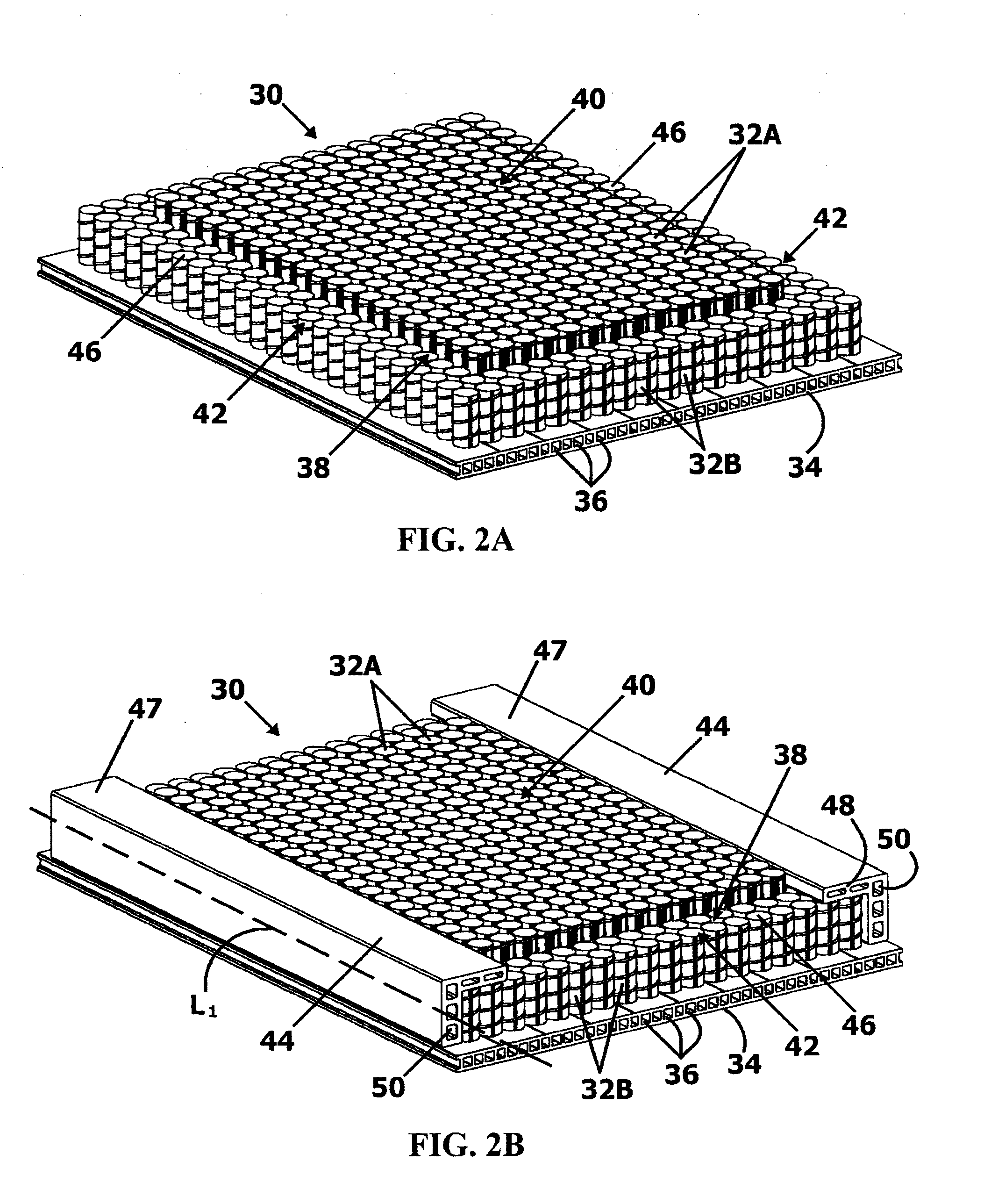
[0012]The stepped-edge disposed in the innerspring assembly by the arrangement of coil springs or cores may be a single or multiple stepped-edge, which is also called a stair stepped-edge. One or more intermediate areas may be disposed in the innerspring assembly or core. Intermediate areas can provide additional transition areas between the interior area or sleep surface and edge of the innerspring assembly. Providing intermediate areas in the innerspring assembly or core may assist in further reducing the amount of spring material or core to reduce costs while providing a spring-like surface to allow the side-support material to intrude further into the interior area or sleeping surface area of the innerspring assembly or core.

Problems solved by technology

Eliminating border wires may also lessen the overall weight of the innerspring assembly thus saving shipping costs.
However, eliminating border wires may reduce firm edge structure and support.
However, eliminating innerspring coils in the innerspring assembly reduces the sleep surface supported by coil springs.
It may be undesirable, unacceptable, or otherwise impractical to reduce the sleep surface of an innerspring assembly by eliminating perimeter innerspring coils.
As one example, basic foam side-supports that are not engineered for longevity can incur compression set over time.
This may be unacceptable for edge-support for an innerspring assembly.

Method used


Image

  • Stepped-edge and side-support members, assemblies, systems, and related methods, particularly for bedding and seating
  • Stepped-edge and side-support members, assemblies, systems, and related methods, particularly for bedding and seating
  • Stepped-edge and side-support members, assemblies, systems, and related methods, particularly for bedding and seating

Examples


Embodiment Construction

[0008]Embodiments in the detailed description include stepped-edge and side-support members, systems, assemblies, and related methods for an innerspring assembly or other core. The innerspring assemblies or cores can be employed for bedding and seating assemblies and applications, as examples. In one embodiment, an innerspring assembly or core is provided having an interior area of a first height surrounded by one or more exterior, perimeter area(s) of shorter height(s) than the interior area to provide a stepped-edge innerspring assembly or core. At least a portion of side-support members are placed onto at least a portion of the top surface of the perimeter area to provide edge-support for the innerspring assembly or core. In this manner, a greater portion of the side-support members can be disposed in the sleeping area of the innerspring assembly or core since the underlying perimeter area provides spring or spring-like support to the side-support members. Further, this support c...


PUM

PropertyMeasurementUnit
Fractionaaaaaaaaaa
Fractionaaaaaaaaaa
Areaaaaaaaaaaa

Abstract

Stepped-edge and side-support members, systems, assemblies, and related methods for an innerspring assembly or other core are disclosed. In one embodiment, an innerspring assembly or core is provided having an interior area of a first height surrounded by one or more exterior, perimeter area(s) of shorter height(s) to provide a stepped-edge innerspring assembly or core. At least a portion of side-support members are placed onto at least a portion of the top surface of the perimeter area to provide edge-support for the innerspring assembly or core. In this manner, a greater portion of the side-support members can be disposed in the sleeping area of the innerspring assembly or core since the underlying perimeter area provides spring support to the side-support members. Further, this support can assist in retention and / or recovery of the shape of the side-support members to further prevent or reduce compression set of the side-support members.

Description

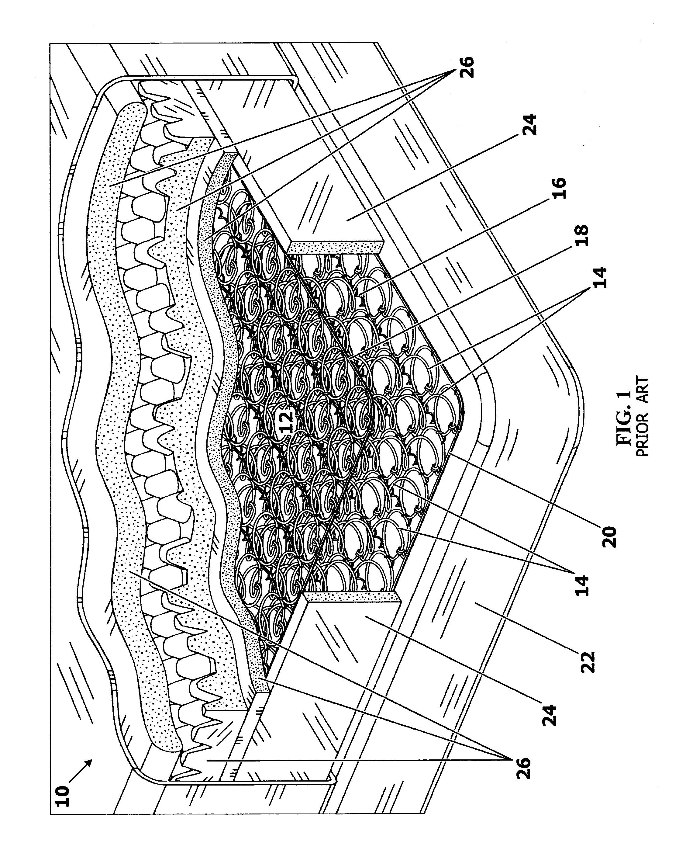
RELATED APPLICATION[0001]The present application claims priority to U.S. Provisional Patent Application Ser. No. 61 / 219,090, filed on Jun. 22, 2009, entitled “Stepped-Edge and Side-Support Members, Assemblies, Systems, and Related Methods, Particularly for Bedding and Seating,” which is incorporated herein by reference in its entirety.BACKGROUND[0002]1. Field of the Disclosure[0003]The technology of the disclosure relates to stepped-edge and side-support members, assemblies, systems, and related methods and which may be employed in bedding and seating applications to provide support, including edge support.[0004]2. Technical Background[0005]Innerspring assemblies for mattresses or seating structures can be composed of a plurality of spring coils tied together in a matrix or array. An example of such an innerspring assembly in the prior art is illustrated by the mattress 10 of FIG. 1. As illustrated therein, a mattress innerspring 12 is provided. The innerspring 12 is comprised of a ...

Claims


Application Information

Patent Timeline
IPC IPC(8): A47C27/05A47C23/00A47C23/04A47C27/04A47C27/14B68G7/06B68G9/00
CPCY10T29/481A47C27/04A47C27/056A47C27/066
Inventor WITHERELL, TIMOTHY MICHAELYOUNG, JULIAN THOMASPAGE, CHRISTOPHER DEANSOBRAN, IVANHENDERSON, RANDAL LEE
Owner NOMACO
Learn More