
Tie foundation for a railway tie

a technology for tie foundations and railways, applied in the direction of railway tracks, lamination, track maintenance, etc., can solve the problems of insufficient resistance of tie foundations and early destruction of tie foundations

Inactive Publication Date: 2010-12-23
GETZNER WERKSTOFFE HOLDING GMBH
View PDF17 Cites 4 Cited by
  • Summary
  • Abstract
  • Description
  • Claims
  • Application Information

AI Technical Summary

Benefits of technology

[0010]The object of the invention is to provide an improvement of generic tie foundations, which contributes to the avoidance of the above-mentioned problems or at least to a reduction in them.
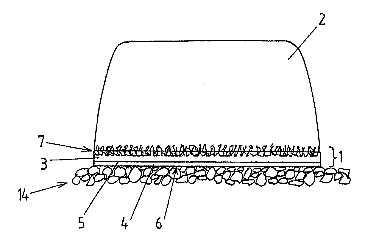
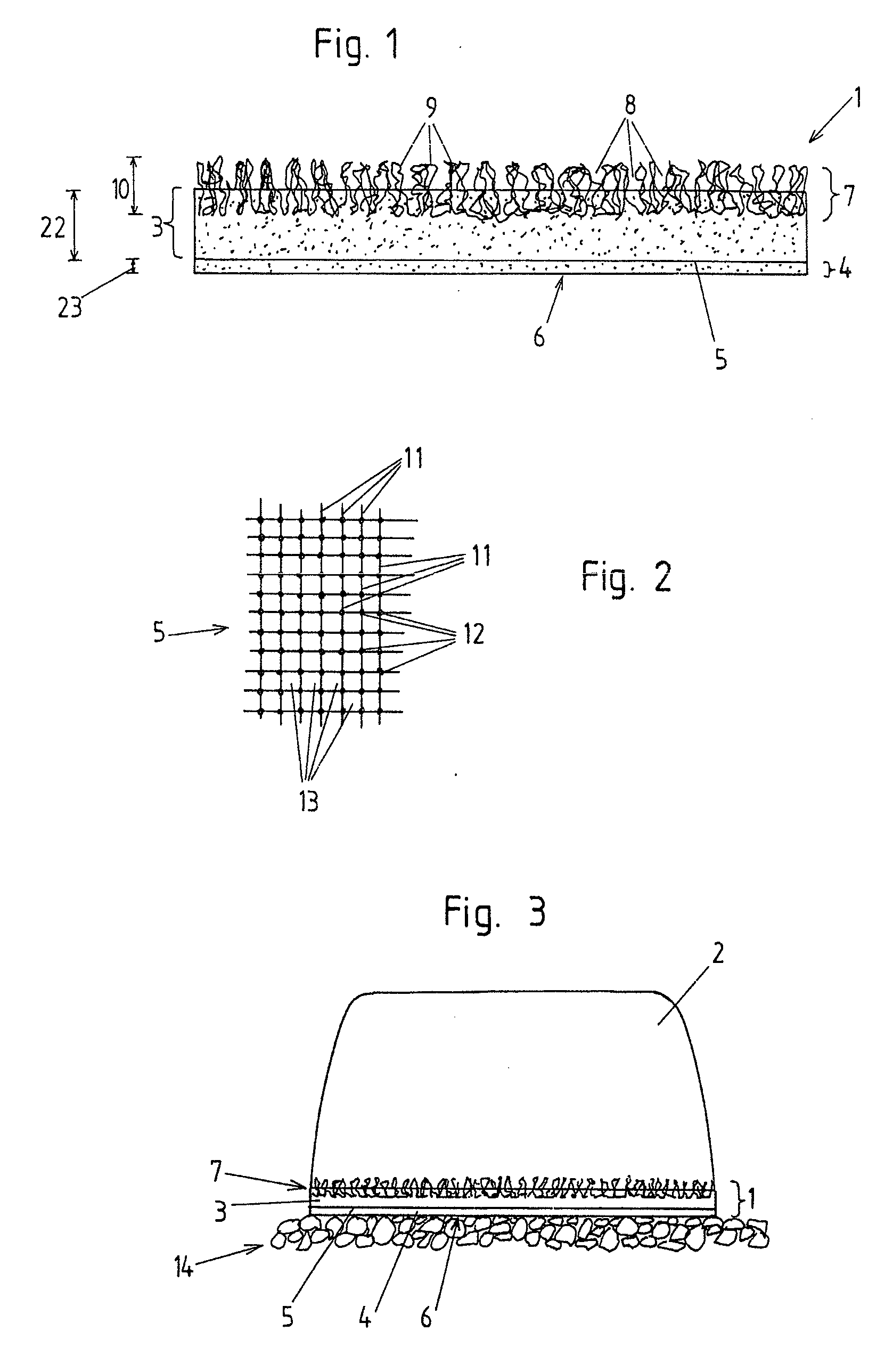
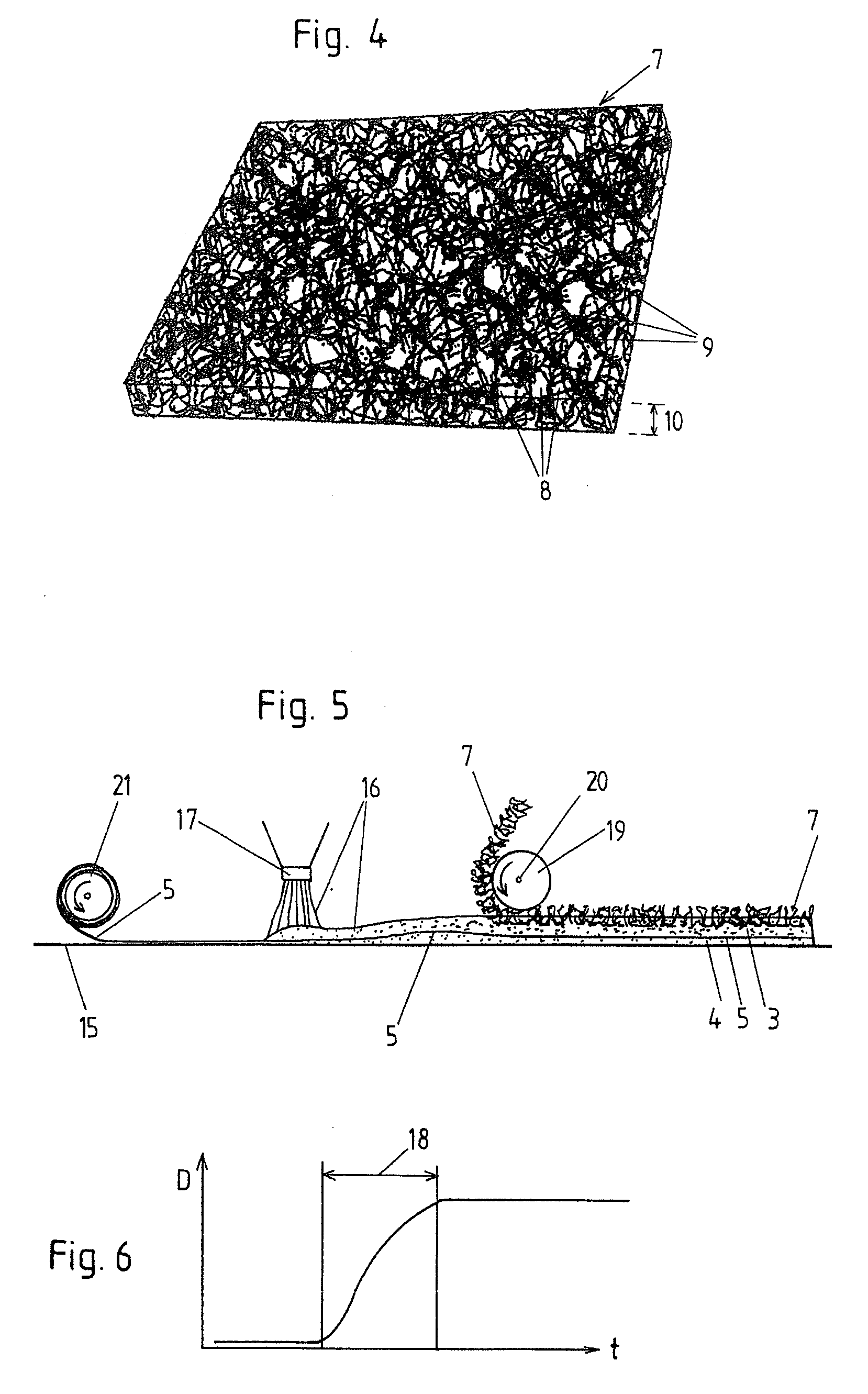
[0012]Therefore, it is provided that the second elastic layer, particularly at least at the side facing away from and / or opposite the railway tie in the operational position, forms an exterior surface of the tie foundation, with the gravel, upon which in the operational position the tie foundation rests together with the railway tie, directly contacting said elastic exterior surface of the second layer of the tie foundation. This way, the required resistance against lateral displacement can be maintained without any problems. The fibrous material of the reinforcement layer also prevents any excessive penetration of the gravel or foundation into the tie foundation such that an early destruction of the tie foundation is prevented. By embedding the fibrous material of the reinforcement layer between the first elastic layer and the second elastic layer the threads of the fibrous material cannot be pushed apart as easily as in a fibrous layer adhered to the exterior surface layer of the tie foundation from the bottom such that by the embedding, a reinforcement layer is formed of particular tensile strength, which prevents any further penetration of the railway gravel into the tie foundation particularly well.
[0024]In this method, in order to embed a connection layer in the first elastic layer of the tie foundation, it may be provided that during the reaction of the reaction mixture, preferably in a foaming phase or a rising phase of the reaction mixture, the connection layer can be impressed into the reaction mixture, preferably by at least 20% or at least 40% of the thickness of the connection layer. Here, it may be provided that by the impression of the connection layer into the reaction mixture the reinforcement layer may be pressed in the direction towards the foundation and / or the floating of the reinforcement layer be limited. By the latter measure it can be prevented that the reinforcement layer floats too much in the reaction layer.

Problems solved by technology

It has been shown that in the generic tie foundations of prior art the penetration of the gravel into the tie foundation is insufficiently prevented, which may lead to an early destruction of the tie foundation.
Furthermore, it has shown that frequently problems occur from an insufficient resistance of the tie foundation against lateral displacement.

Method used


Image

  • Tie foundation for a railway tie
  • Tie foundation for a railway tie
  • Tie foundation for a railway tie

Examples


Embodiment Construction

[0034]In a preferred exemplary embodiment according to FIG. 1, the reinforcement layer 5 is arranged between the first elastic layer 3 and the second elastic layer 4 of the tie foundation 1. Here, the second elastic layer 4 forms the lower exterior surface 6 of the tie foundation 1, i.e. in the operating position facing away from the railway tie and / or opposite thereto. On the opposite side, i.e. the one pointing towards the railway tie 2 in the operational position, the tie foundation 1 is provided with the connection layer 7, which in the exemplary embodiment shown here is embedded in the first elastic layer 3. The connecting layer 7 forms a spatially expanded grid made from threads 9. The clear spaces 8 are formed between the threads 9, into which the material of the railway tie can penetrate in the sense of a form-fitting, material-fitting, or fabric-fitting connection. In order to fasten it to the first layer 3, the connection layer 7 is embedded by approx. 40% of its thickness...


PUM

PropertyMeasurementUnit
Fractionaaaaaaaaaa
Fractionaaaaaaaaaa
Widthaaaaaaaaaa

Abstract

A tie foundation (1) for a railway tie (2) having at least a first elastic, preferably elastomer layer (3) and at least a second elastic, preferably elastomer layer (4), with a reinforcement layer (5) being embedded between the first elastic layer (3) and the second elastic layer (4), with the second elastic layer (4) forming an outer surface (6) of the tie foundation (1) and the reinforcement layer (5) comprising a fibrous material.

Description

CROSS-REFERENCE TO RELATED APPLICATIONS[0001]This application is a continuation of PCT / AT2009 / 000077, filed Feb. 26, 2009, which claims the benefit of Austrian Application No. A365 / 2008, filed Mar. 6, 2008, both of which are incorporated herein by reference as if fully set forth.BACKGROUND[0002](a) Field of the Invention[0003]The present invention relates to a tie foundation for a railway tie having at least a first elastic, preferably elastomer layer, and at least a second elastic, preferably elastomer layer, with a reinforcement layer being embedded between the first elastic layer and the second elastic layer. Additionally, the invention also relates to a method to produce a tie foundation as well as an arrangement comprising a railway tie and a tie foundation.[0004](b) Description of the State of the Art[0005]As known per se, a tie foundation represents an elastic underlayment, arranged and / or to be arranged underneath a railway tie, which is arranged at said railway tie, e.g., b...

Claims


Application Information

Patent Timeline
IPC IPC(8): E01B1/00
CPCE01B3/46E01B1/00E01B19/00
Inventor POTOCAN, STEFANDIETRICH, MARTIN
Owner GETZNER WERKSTOFFE HOLDING GMBH
Learn More