Electric actuator for driving a home-automation screen

a technology of electric actuator and homeautomation, which is applied in the direction of electrical apparatus, dynamo-electric machines, building components, etc., can solve the problems of secondary braking torque, drawbacks of conventional spring brake design as described in the preceding example, and apply secondary braking torque, so as to increase the contact force

Active Publication Date: 2010-12-23
SOMFY ACTIVITES SA
View PDF8 Cites 15 Cited by
  • Summary
  • Abstract
  • Description
  • Claims
  • Application Information

AI Technical Summary

Benefits of technology

[0010]an outlet part connected to the screen and suitable for coming into contact with at least one tab of the spring in such a manner as to drive the spring in

Problems solved by technology

Since the force exerted on the outlet part is asymmetrical, it results in a radial force being applied to said outlet part and thus in secondary braking torque being applied.
The way in which conventional spring brake designs as described in the preceding examples operate suffers from drawbacks in certain configurations.
Unfortunately, the existen

Method used


Image

  • Electric actuator for driving a home-automation screen
  • Electric actuator for driving a home-automation screen
  • Electric actuator for driving a home-automation screen

Examples


first embodiment

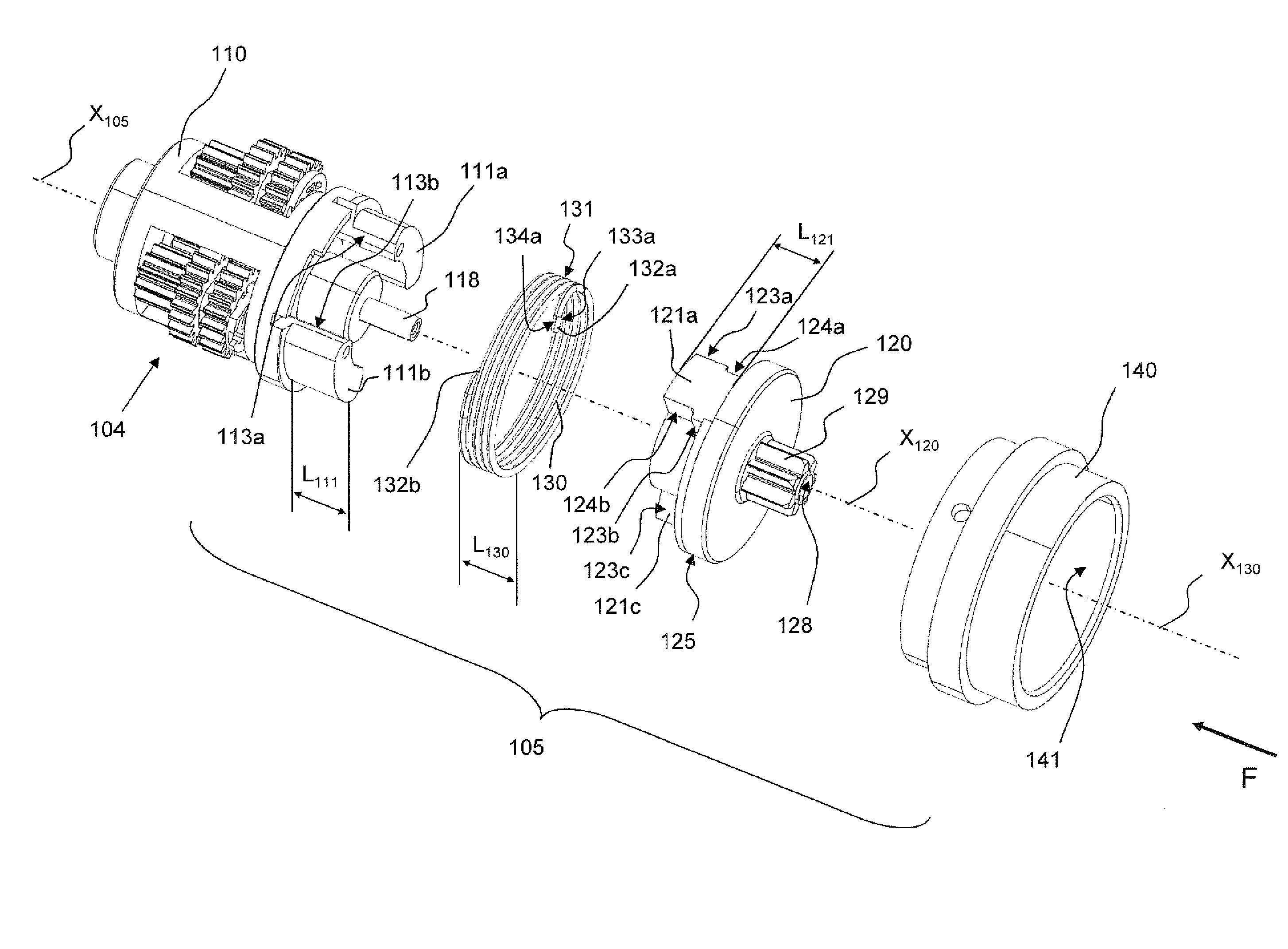
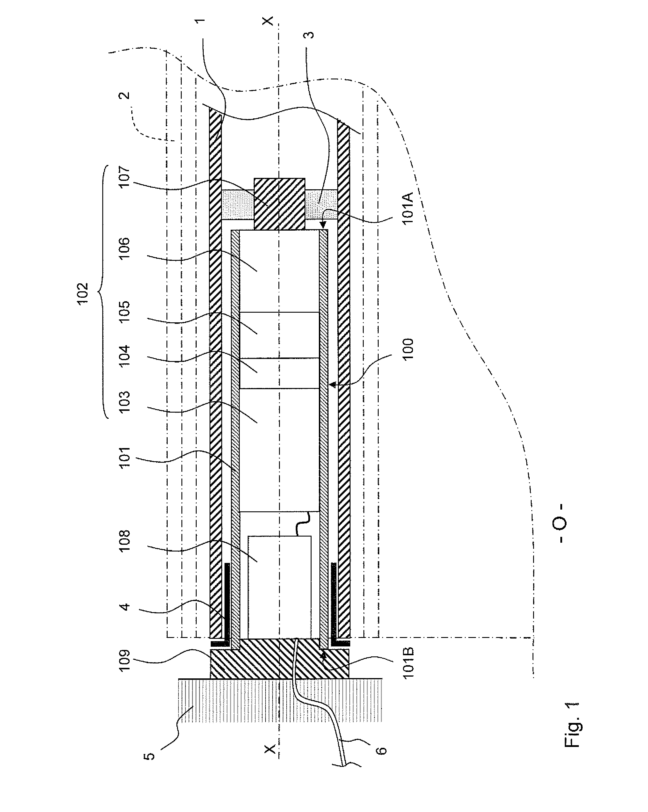
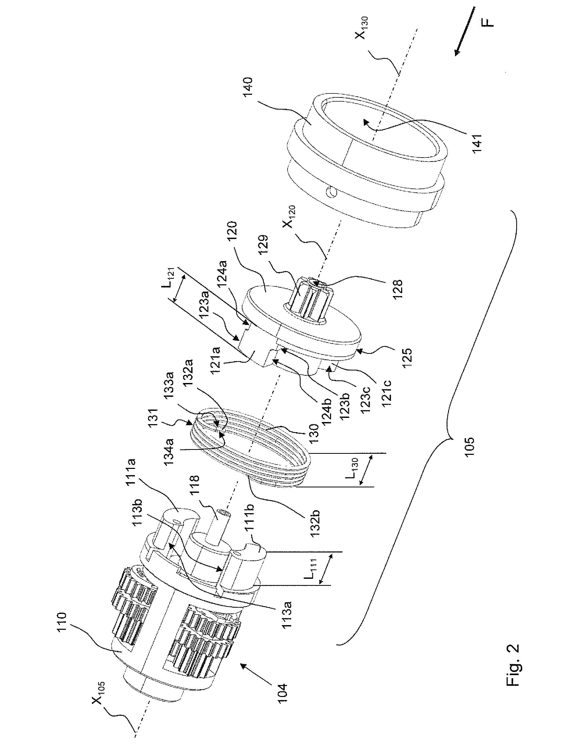
[0042]FIGS. 2 to 4 more particularly show the structure of the spring brake 105 in the invention. As shown in FIG. 1, a rotor of the motor 103 drives an epicyclic gear train of the first gearbox stage 104. The cylinder 110 of the epicyclic train that carries three planet gears also forms an inlet part of the brake 105. The brake 105 includes a helical spring 130 having its turns centered on an axis X130 that coincides with the axis X-X when the brake 105 is in place, as shown in FIG. 1. Said spring is mounted in tight-fitting manner inside a bore 141 in a friction part 140. In other words, the outside envelope 131 of the spring 130, which envelope is defined by the outside generator lines of its turns, bears against the radial surface of the bore 141, thereby tending to secure together the spring 130 and the part 140 by friction.

[0043]Each end of the spring 130 forms a tab 132a, 132b extending radially towards the axis X130 and towards the inside of the spring, from its turns.

[0044]...

second embodiment

[0070]X-X when the brake 105 is in place as shown in FIG. 1. The axes X230 and X-X coincide with the central axis X105 of the brake 105 when an actuator 100 incorporating the brake 105 of this second embodiment is in the assembled configuration.

[0071]The spring 230 is mounted in tight-fitting manner inside a bore 241 in a friction part 240. In other words, the outside envelope 231 of the spring 230, which envelope is defined by the outside generator lines of its turns, bears against the radial surface of the bore 241, thereby tending to secure together the spring 230 and the part 240 by friction.

[0072]Each end of the spring 230 forms a tab 232a, 232b extending radially towards the axis X230 and towards the inside the spring, from its turns.

[0073]The inlet part 210 is provided with a protuberance or “tooth”211a that fits into the helical spring 230, between the tabs 232a and 232b. Said tooth 211a has two faces 213a, 213b suitable for being in contact respectively with a surface 233a ...


PUM


Abstract

This electric actuator for driving a home-automation screen is provided with a spring brake (105) comprising a helical spring (130), a friction part (140) having a friction surface (141) against which the helical spring (130) bears radially. Said brake further comprises an inlet part (110) suitable for driving the spring in rotation in a direction reducing the contact force between the spring (130) and the friction part (140), and an outlet part (120) connected to the screen.
While the screen is being lowered, the inlet part (110; 210) drives the spring (130; 230) in rotation with the contact force being decreased to the extent that the outlet part (120; 220) is released in rotation, without direct contact between the inlet part and the outlet part. The inlet part (110; 210) has at least two contact surfaces (113a, 113d; 213b, 217c) suitable for transmitting drive torque (CM) for raising the screen (2), by direct contact, to at least two corresponding contact surfaces (123a, 123d; 223b, 227a) of the outlet part (120; 220).

Description

TECHNICAL FIELD[0001]The present invention relates to an electric actuator for driving a home-automation screen, of any of the following types: roller blind, shade, curtain, gate, projection screen, or garage door. The actuator of the invention is provided with a spring brake. This type of brake is more particularly adapted to tubular motors.STATE OF THE ART[0002]Use of a helical-spring brake in actuators for home-automation screens is known, in particular from Patent Document FR B 2 610 668. In that document, a helical spring is mounted in a friction part. At least one turn of the spring is stressed radially by a bore in the friction part. Each end of the spring forms a tab extending radially towards the inside of the spring. Each tab can be moved in order to drive the spring in rotation about its axis. The inlet part, the outlet part, and the spring are arranged specifically to obtain the following dynamic behavior: action from the inlet part situated on one side of the first tab ...

Claims


Application Information

Patent Timeline
IPC IPC(8): H02K7/102
CPCE06B9/72E06B9/84E06B9/90F16D67/00F16D49/04F16D51/00F16D51/02E06B2009/905
Inventor LAGARDE, ERICMENETRIER, DIDIER
Owner SOMFY ACTIVITES SA
Why Eureka
Try Eureka