Illumination device and liquid crystal display device

illumination device technology, applied in non-linear optics, lighting and heating apparatus, instruments, etc., can solve the problem of low contrast (dynamic range) of an image displayed by a liquid crystal display device, and achieve the effect of reducing the width of the partition wall, preventing luminance irregularities, and efficiently providing diffusion sections

Inactive Publication Date: 2010-12-23
SHARP KK
View PDF6 Cites 12 Cited by
  • Summary
  • Abstract
  • Description
  • Claims
  • Application Information

AI Technical Summary

Benefits of technology

[0009]In view of the above-described problems, preferred embodiments of the present invention provide an illumination device capable of conducting a luminance adjustment for each illumination area, wherein a luminance irregularity and a color irregularity are prevented.
[0011]With the above configuration, the light emitted from the light source of the illumination area is diffused by the diffusion section provided at the vertex of the partition wall. As a result, it is possible to prevent a luminance irregularity when adjusting the luminance in each adjoining illumination area.
[0012]Further, when providing the diffusion section at the vertex of the partition wall, it is not necessary to increase the width of the partition wall in order to add the diffusion section. Further, by providing the diffusion section at the vertex of the partition wall, it is possible to dispose paths (i.e., light paths) of the light emitted from the adjoining illumination areas symmetrically with respect to the vertex of the partition wall. As a result, compared to a configuration in which the diffusion section is not provided at the vertex of the partition wall, it is possible to provide the diffusion section efficiently and to efficiently prevent a luminance irregularity caused when adjusting the luminance in each adjoining illumination area.

Problems solved by technology

However, it is a problem that the contrast (dynamic range) of an image displayed by a liquid crystal display device is low compared to an image of a CRT.

Method used


Image

  • Illumination device and liquid crystal display device
  • Illumination device and liquid crystal display device
  • Illumination device and liquid crystal display device

Examples


first preferred embodiment

[0022]A preferred embodiment of the present invention is described below with reference to the attached drawings FIGS. 1 to 3C.

[0023]The following is an explanation, referring to FIGS. 1 and 2, of an illumination device 1 in accordance with a preferred embodiment of the present invention.

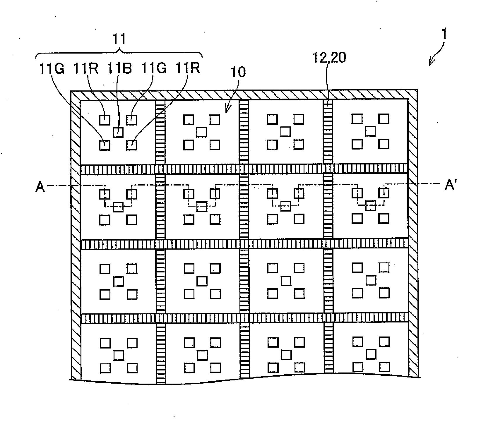
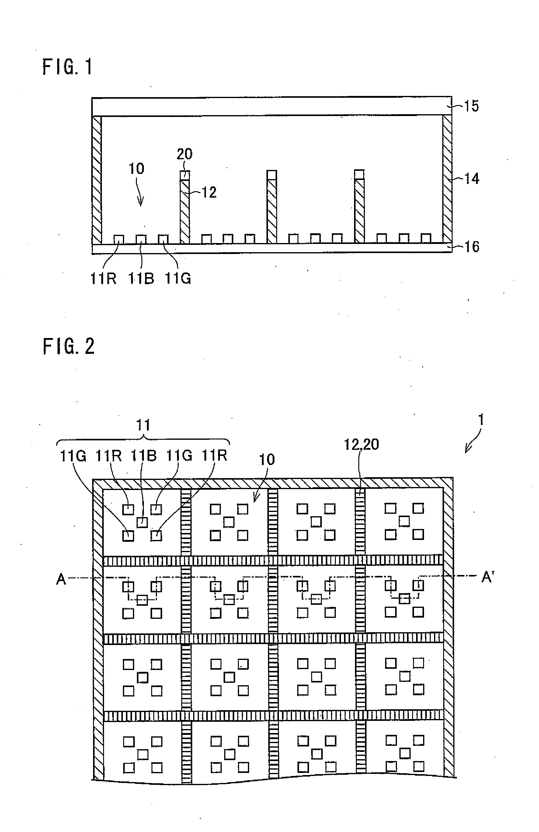
[0024]FIG. 2 is a plan view of the illumination device 1 in accordance with a preferred embodiment of the present invention. FIG. 1 is a cross-sectional view of FIG. 2 along the line A-A′.

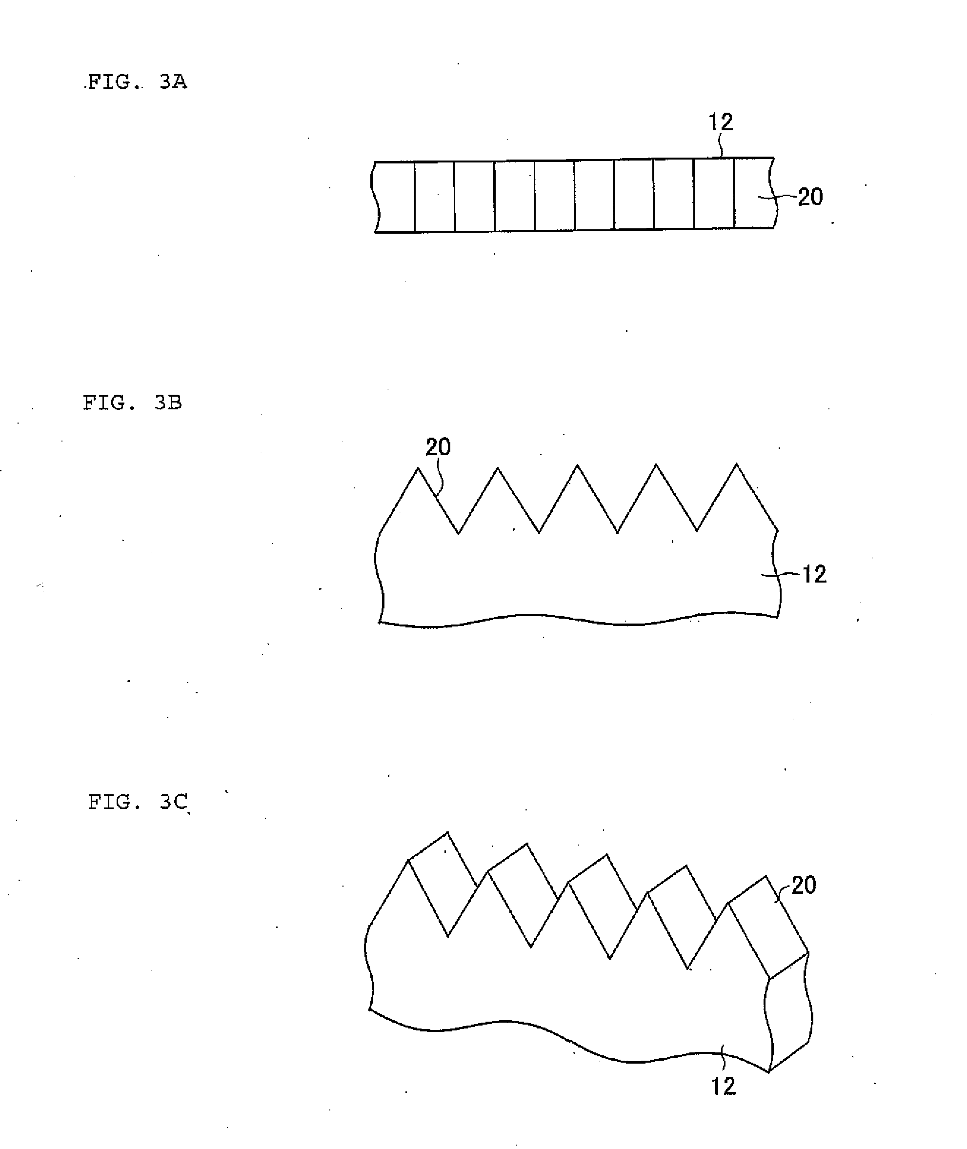
[0025]As shown in FIG. 2, light source blocks 10 (illumination areas), on which LEDs 11 (“LED” standing for light-emitting diode) as described below are mounted, are arranged in a matrix configuration on the illumination device 1. Further, between the light source blocks 10, a first partition wall 12, which has a projection section 20 (to be described below) thereon, is provided. The first partition walls 12 are arranged in a lattice-shaped configuration over the illumination device 1. In addition, around the illum...

second preferred embodiment

[0051]Next, a second preferred embodiment of the present invention is described below with reference to FIGS. 1 and 4A to 4C. A projection element in the second preferred embodiment preferably has a shape different from that in the first preferred embodiment. Because the first preferred embodiment and the second preferred embodiment are similar in all other respects, the explanations on the same subject matter will not be repeated here.

[0052]FIG. 4A is a plan view of a vertex of a first partition wall 12 on which a projection section (diffusion section) 21 is provided, in place of the projection section 20 previously described. FIG. 4B is a side view of the first partition wall 12 and of the projection section 21 shown in FIG. 4A. FIG. 4C is a perspective view of the projection section 21 shown in FIG. 4A.

[0053]As shown in FIGS. 4A-4C, with the projection section 21, a surface parallel to a side surface of the first partition member 12 is formed with determined pitches so as to have...

third preferred embodiment

[0060]Next, a third preferred embodiment of the present invention is described below with reference to the attached FIG. 1 and FIGS. 5A to 5C. A projection element in the third preferred embodiment preferably has a shape that is different from those in the first and second preferred embodiments. Because the third preferred embodiment is similar to the first and second preferred embodiments in all other respects, the explanations on the same subject matter will not be repeated here.

[0061]FIG. 5A is a plan view of the vertex of the first partition wall 12 on which a projection section 22 is provided, in place of the projection section 20 or the projection section 21 previously described. FIG. 5B is a side view of the first partition wall 12 and of the projection section 22 shown in FIG. 5A. FIG. 5C is a perspective view of the projection section 22 shown in FIG. 5A.

[0062]As shown in FIGS. 5A-5C, the projection section 22 is hemispherical or substantially hemispherical. On an upper sur...


PUM

PropertyMeasurementUnit
heightaaaaaaaaaa
heightaaaaaaaaaa
angleaaaaaaaaaa

Abstract

An illumination device includes a plurality of light source blocks defined by a first partition wall and a second partition wall, the light source blocks being provided with LEDs. The illumination device is capable of adjusting a luminance of each of the plurality of light source blocks. A projection section to diffuse the light is provided on a vertex of the first partition wall. As a result, it is possible to prevent a luminance irregularity and a color irregularity from occurring between illumination areas when adjusting the respective luminance in each of the plurality of illumination areas.

Description

BACKGROUND OF THE INVENTION[0001]1. Field of the Invention[0002]The present invention relates to a backlight comprising a plurality of light sources and to a liquid crystal display device provided with the backlight.[0003]2. Description of the Related Art[0004]Liquid crystal display devices are characterized, among other aspects, by thinness, low electricity consumption and high definition, and are getting more and more popular in the field of televisions, which conventionally use mainly cathode ray tubes (CRT), as the development of production methods of the liquid crystal display devices makes it possible to produce bigger screens. However, it is a problem that the contrast (dynamic range) of an image displayed by a liquid crystal display device is low compared to an image of a CRT. As a result, in recent years, a lot of efforts have been made to develop a technology allowing to increase image quality through an increase of the contrast of the liquid crystal display device.[0005]F...

Claims


Application Information

Patent Timeline
Patent Type & Authority Applications(United States)
IPC IPC(8): G02F1/1335F21V11/00F21V9/00
CPCG02F1/133603G02F1/133605G02F1/133606G02F2001/133613G02F1/133611G02F1/133621G02F2001/133601G02F1/133609G02F1/133601G02F1/133613
Inventor TANAKA, ATSUYUKIMASUDA, TAKESHI
Owner SHARP KK
Why Eureka
Try Eureka