Arc flash detection system

a detection system and arc flash technology, applied in the field of arc flash detection, can solve the problems of erroneous arc detection, slow response time, and insufficient speed to mitigate an arc flash, and achieve the effect of mitigating the arc flash

Active Publication Date: 2010-12-23
GENERAL ELECTRIC CO
View PDF16 Cites 42 Cited by
  • Summary
  • Abstract
  • Description
  • Claims
  • Application Information

AI Technical Summary

Benefits of technology

[0009]In another embodiment, an intelligent grid is proposed. The intelligent grid includes an electrical distribution system coupled to the grid and comprising a plurality of devices electrically coupled to perform a pre-determined function. A remote diagnostic system is coupled to the grid to monitor one or more characteristics of the grid. The intelligent gr

Problems solved by technology

However, such techniques have slow response times and are not fast enough to mitigate an arc flash.
However, such a method of light detection may lead to erroneous arc detection when stray light or light from other sources is detected.
Further, such methods do not provide location of the arcing event.
Such methods, howe

Method used


Image

  • Arc flash detection system
  • Arc flash detection system
  • Arc flash detection system

Examples


Embodiment Construction

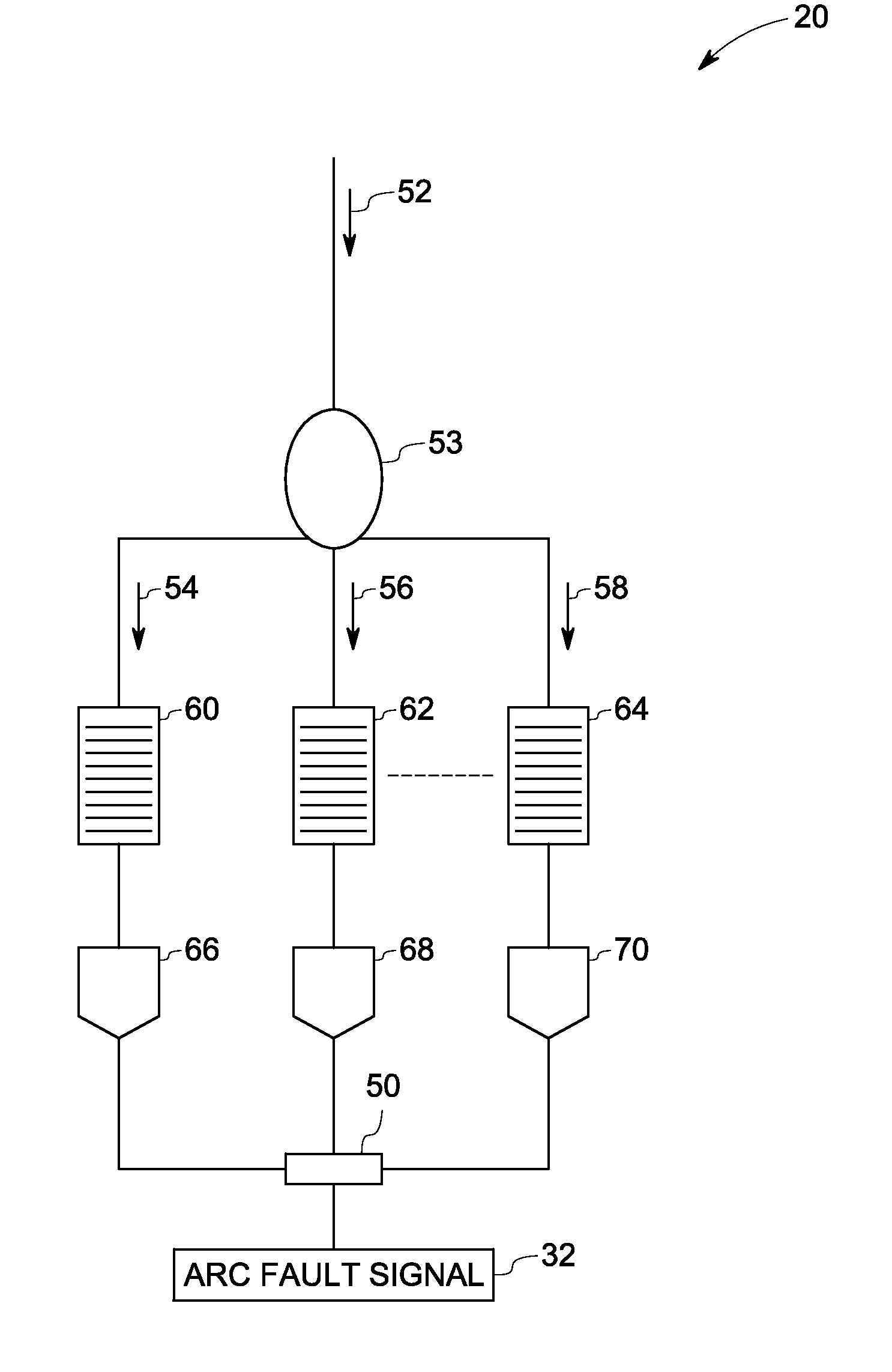
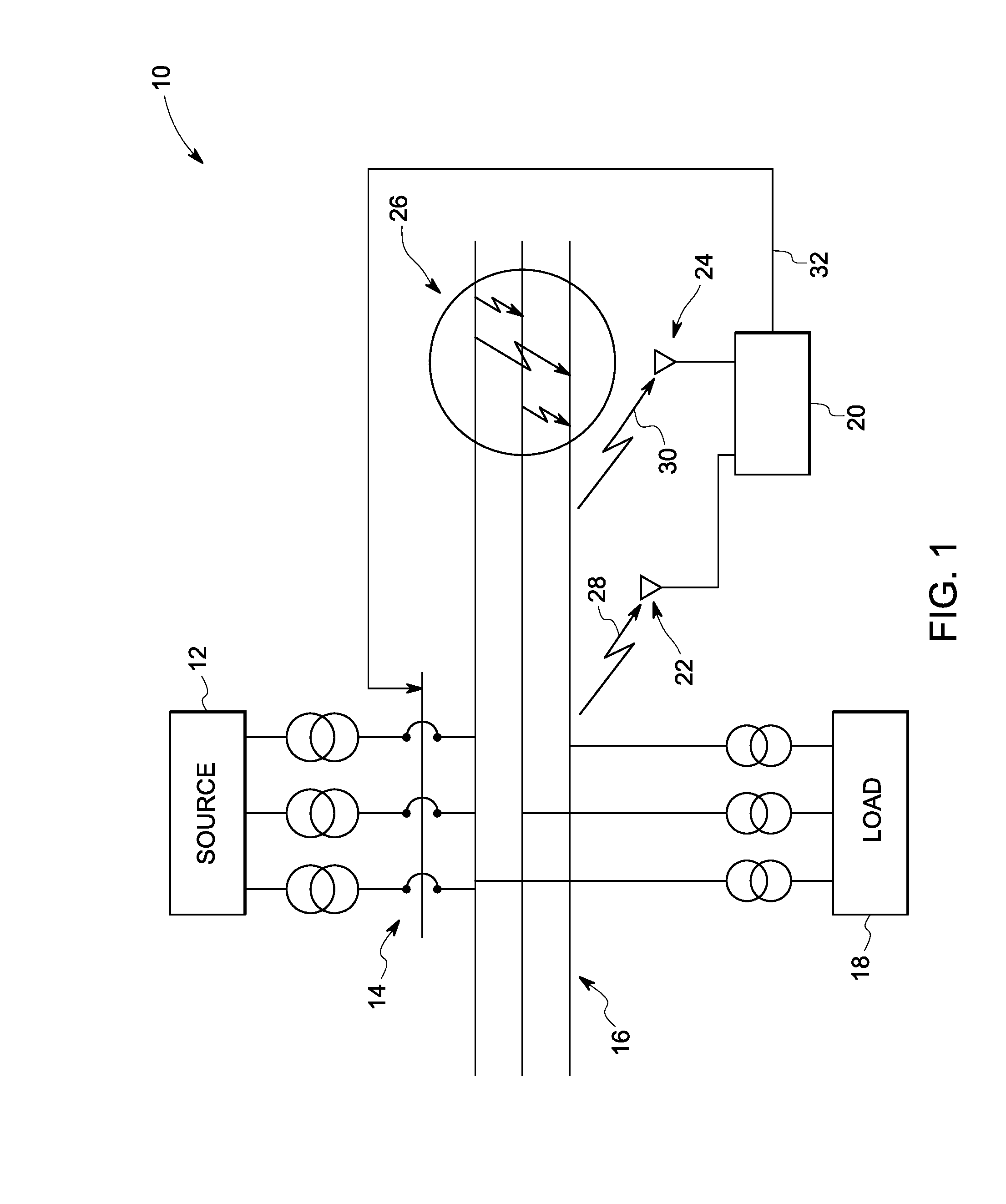
[0021]FIG. 1 is a schematic diagram of an exemplary electrical distribution system. Electrical distribution system 10 includes an electrical power source 12, protective device 14, bus bars 16 and load 18. In an exemplary embodiment an arc flash detection system 20 is implemented in the electrical distribution system 10. Fiber sensors 22 and 24 are coupled to the arc flash detection system 20 and configured to detect an arc flash event 26. An example of an electrical power source 12 includes a generator configured to deliver electrical power through a protective device 14 to bus bars 16. An example of a protective device 14 includes a circuit breaker that may be operated through electrical command signals. A load 18 receives electrical power from the source 12 via the bus bars 16.

[0022]An arc flash may occur in any location of the system 10 between at least two current carrying bus bars / conductors. Further the arcing event may occur between current carrying bus bars / conductor and gro...


PUM


Abstract

An apparatus to detect arc is presented. The apparatus includes a fiber sensor to detect characteristics of an arc flash and a processor to process at least two characteristics of the arc flash. The processor is further configured to generate an arc fault signal. A protective device is configured to mitigate the arc flash based on the arc fault signal.

Description

BACKGROUND[0001]The invention generally relates to arc flash detection, particularly to arc detection using multiple parameters of an arc flash.[0002]Electric power circuits and switchgear have conductors separated by insulation. Air space often serves as part or all of this insulation in some areas. If the conductors are too close to each other or voltage exceeds the insulation level, an arc can occur between conductors. Air or any other insulation (gas, solid, or liquid) between conductors can become ionized, making the insulation conductive thereby enabling an arcing event. Arc event induces temperatures that can reach as high as 20,000° C., vaporizing conductors and adjacent materials, and releasing an explosive energy that destroys surrounding circuits.[0003]Arc flash is the result of a rapid energy release due to an arcing fault between phase-phase, phase-neutral, or phase-ground. An arc flash can produce high heat, intense light, pressure waves, and sound / shock waves similar ...

Claims


Application Information

Patent Timeline
IPC IPC(8): H02H9/08G01R31/00
CPCH02H1/0023H01H33/26
Inventor WU, JUNTAOGUIDA, RENATOXIA, HUAGARRITY, JOHN THOMAS
Owner GENERAL ELECTRIC CO
Why Eureka
Try Eureka