Medical X-ray CT imaging apparatus

a technology of ct imaging and x-ray, which is applied in the direction of patient positioning for diagnostics, instruments, applications, etc., can solve the problems of limiting the mode in which an affected part is disposed with respect to the x-ray source and the x-ray detector, and it is difficult to dispose an upper arm, a hip joint, a chest or the like of a patient in the space between the x-ray source and the x-ray detector, and achieve simpl

Active Publication Date: 2010-12-23
MORITA MFG CO LTD
View PDF7 Cites 29 Cited by
  • Summary
  • Abstract
  • Description
  • Claims
  • Application Information

AI Technical Summary

Benefits of technology

[0043]According to the medical X-ray CT imaging apparatus of the eighteenth aspect, an imaged region can be magnified with a simple structure, which makes it possible to cover a small target area such as an arm...

Problems solved by technology

For this reason, limitations are imposed on a mode in which an affected part is disposed with respect to the X-ray source and the X-ray detector.
For example, the presence of the moto...

Method used


Image

  • Medical X-ray CT imaging apparatus
  • Medical X-ray CT imaging apparatus
  • Medical X-ray CT imaging apparatus

Examples


first preferred embodiment

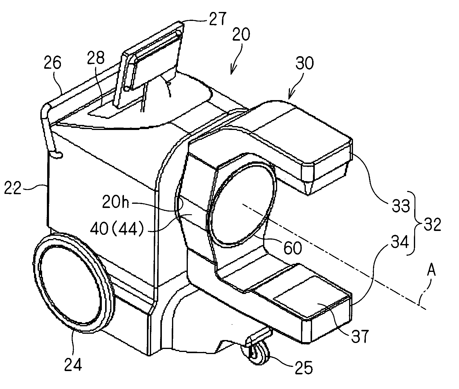
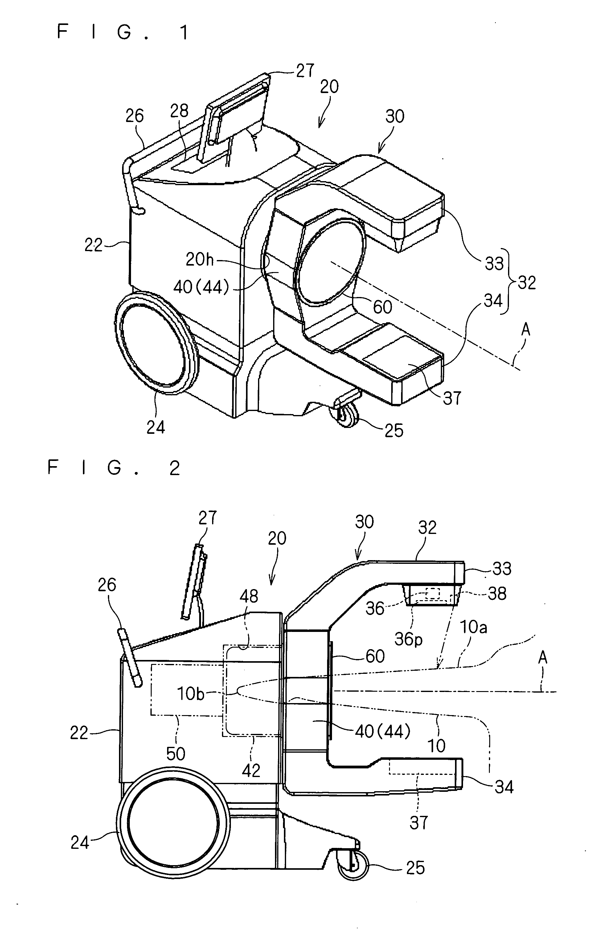
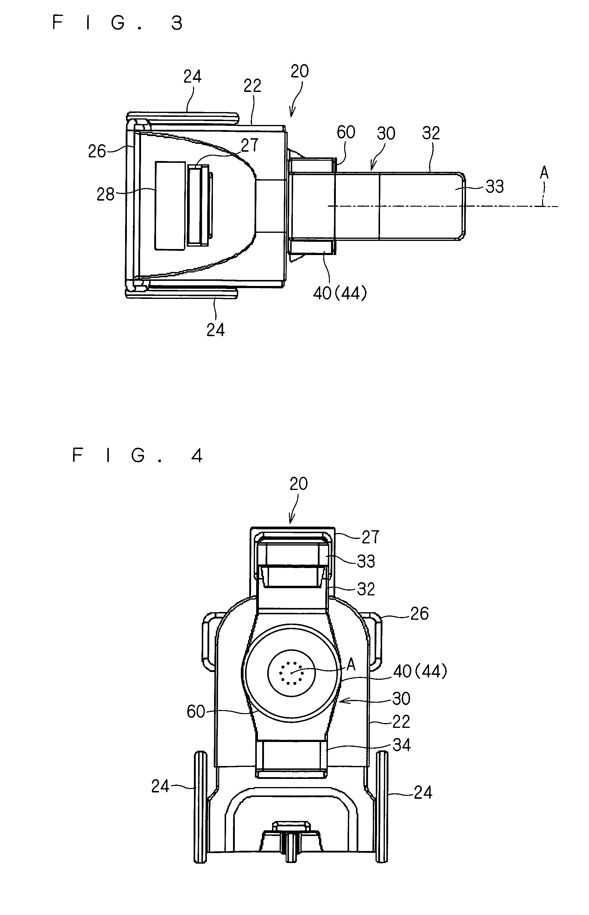
[0089]Hereinafter, description is given of a medical X-ray CT imaging apparatus according to a first preferred embodiment. FIGS. 1 to 5 are views showing a medical X-ray CT imaging apparatus 20 according this preferred embodiment, FIG. 6 is an exploded perspective view showing a support part 30 and a cylindrical body 60 of the medical X-ray CT imaging apparatus 20, and FIGS. 7 and 8 are cross-sectional views of main parts, which show a rotation support part 40 and the cylindrical body 60 of the medical X-ray CT imaging apparatus 20.

[0090]The medical X-ray CT imaging apparatus 20 is an apparatus for performing CT imaging of a part of a patient such as a head, cervical spine, arm joint, finger, breast, lumbar spine, hip joint, knee and leg, and includes a base 22, the support part 30, a rotary drive part 50 and the cylindrical body 60.

[0091]The base 22 is a portion serving as a base to which respective parts constituting the apparatus 20 are directly or indirectly assembled. The suppo...

second preferred embodiment

[0228]A medical X-ray CT imaging apparatus according to the second preferred embodiment is described. Note that in the description of this preferred embodiment, similar elements to those described in the first preferred embodiment are denoted by like reference symbols, and description thereof is omitted. FIGS. 38 to 43 are views showing main parts of the medical X-ray CT imaging apparatus according to the second preferred embodiment. In the medical X-ray CT imaging apparatus, the cylindrical body 660 is attached to the base.

[0229]That is, in the base corresponding to the base 22 according to the first preferred embodiment, a drive part mounting plate 638 is supported such that a given position or position thereof can be changed. A support shaft part 610 is mounted onto and fixed to the drive part mounting plate 638 by screwing or the like, and a rotary drive part 650 such as a motor is mounted and fixed next to the support shaft part 610 through a bracket or the like.

[0230]One end o...


PUM


Abstract

Provided is a medical X-ray CT imaging apparatus including: a base (22); a support part (30) including a support arm part (30) that supports an X-ray source (36) and an X-ray detector (37) so as to be opposed to each other, and a rotation support part that supports the support arm part (32) in a rotatable manner with respect to the base (22); and a rotary drive part that rotatively drives the support part (30). At least one of the base (22) and the rotary support part (40) includes a cavity (48) forming a space around a rotation axis (A). The cavity (48) is provided with a cylindrical body (60) disposed in a rotatable state with respect to the support part (30).

Description

BACKGROUND OF THE INVENTION[0001]1. Field of the Invention[0002]The present invention relates to an X-ray CT imaging apparatus used in medical diagnosis or the like, and more particularly, to an X-ray CT imaging apparatus that takes an image of a part of a patient such as a limb joint and a breast.[0003]2. Description of the Background Art[0004]Conventionally, as an X-ray CT imaging apparatus that takes an image of a part of a patient, there is one disclosed in US 2008 / 260095 A1.[0005]US 2008 / 260095 A1 discloses the portable CT imaging apparatus that takes an image of a head of a patient. In the CT imaging apparatus, an X-ray source and an X-ray detector are supported by a first arm in a state of being arranged so as to be opposed to each other, and the first arm is supported so as to be rotatively driven by a motor. The first arm is rotated in a state where the head is disposed between the X-ray source and the X-ray detector, whereby the X-ray source and the X-ray detector are rota...

Claims


Application Information

Patent Timeline
IPC IPC(8): A61B6/03
CPCA61B6/04A61B6/4441A61B6/4405
Inventor NIIZEKI, RYUICHIRO
Owner MORITA MFG CO LTD
Why Eureka
Try Eureka