Cage for bearing assembly

a bearing assembly and cage technology, applied in the direction of roller bearings, mechanical equipment, rotary machine parts, etc., can solve the problems of limiting the operating envelope of the bearing assembly, cumbersome and time-consuming handling of individual rolling elements, and large amounts of centripetal acceleration, so as to reduce the pv experienced by the bearing cage, increase the outer surface area, and reduce the effect of pv

Inactive Publication Date: 2010-12-23
KOYO BEARINGS NORTH AMERICA LLC
View PDF18 Cites 14 Cited by
  • Summary
  • Abstract
  • Description
  • Claims
  • Application Information

AI Technical Summary

Benefits of technology

[0005]The present invention relates generally to a bearing assembly for use in a transmission including at least one planetary gear set. The bearing assembly includes a bearing cage with increased outer surface area to produce a lower PV during normal operating conditions. Specific ge

Problems solved by technology

During part assembly, handling individual rolling elements is cumbersome and time consuming.
Due to the mass of the bearing cage, the rotation results in large amounts of centripetal acceleration, and consequently, movement of the bearing cage radially outwardl

Method used


Image

  • Cage for bearing assembly
  • Cage for bearing assembly
  • Cage for bearing assembly

Examples


Embodiment Construction

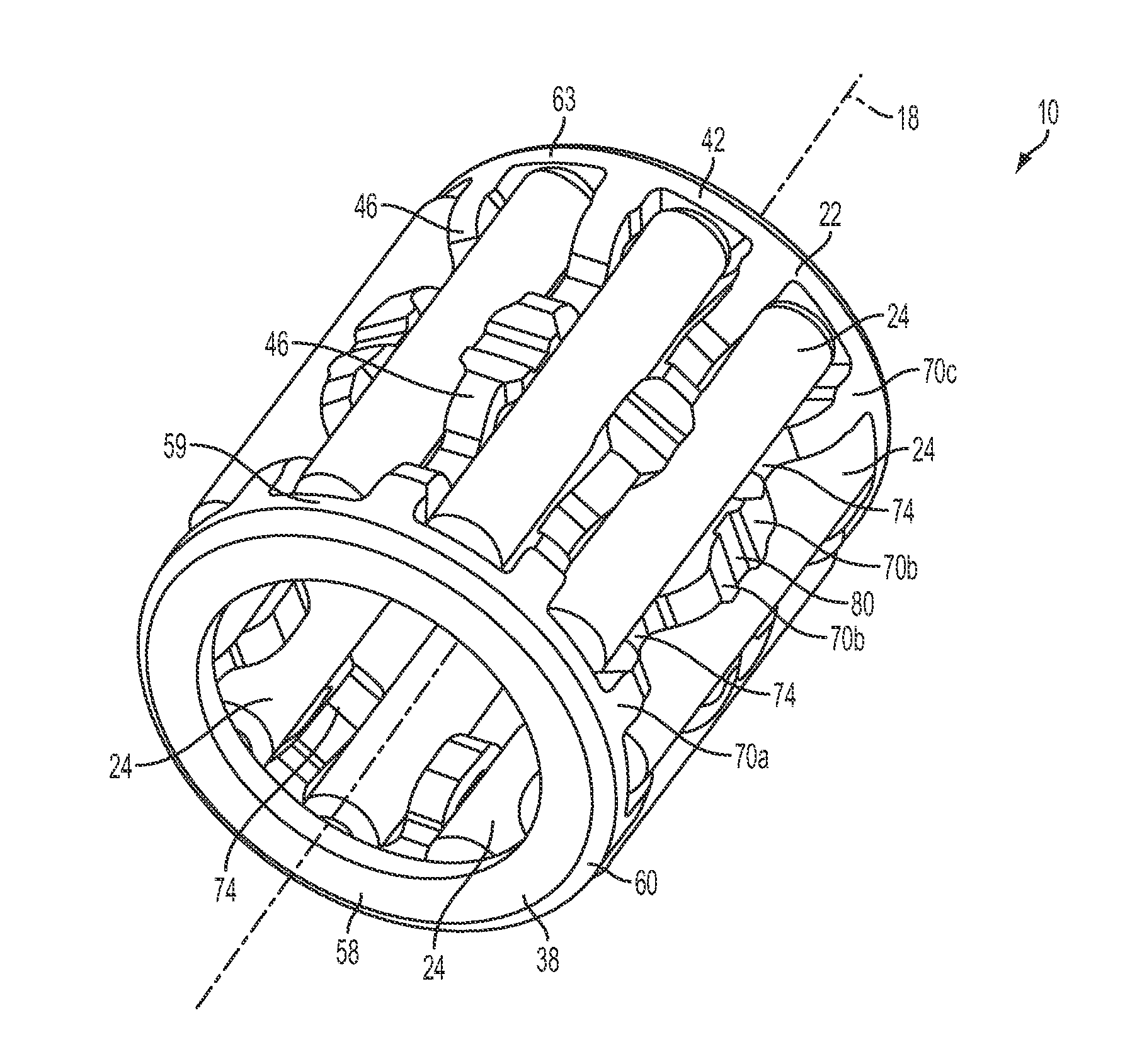
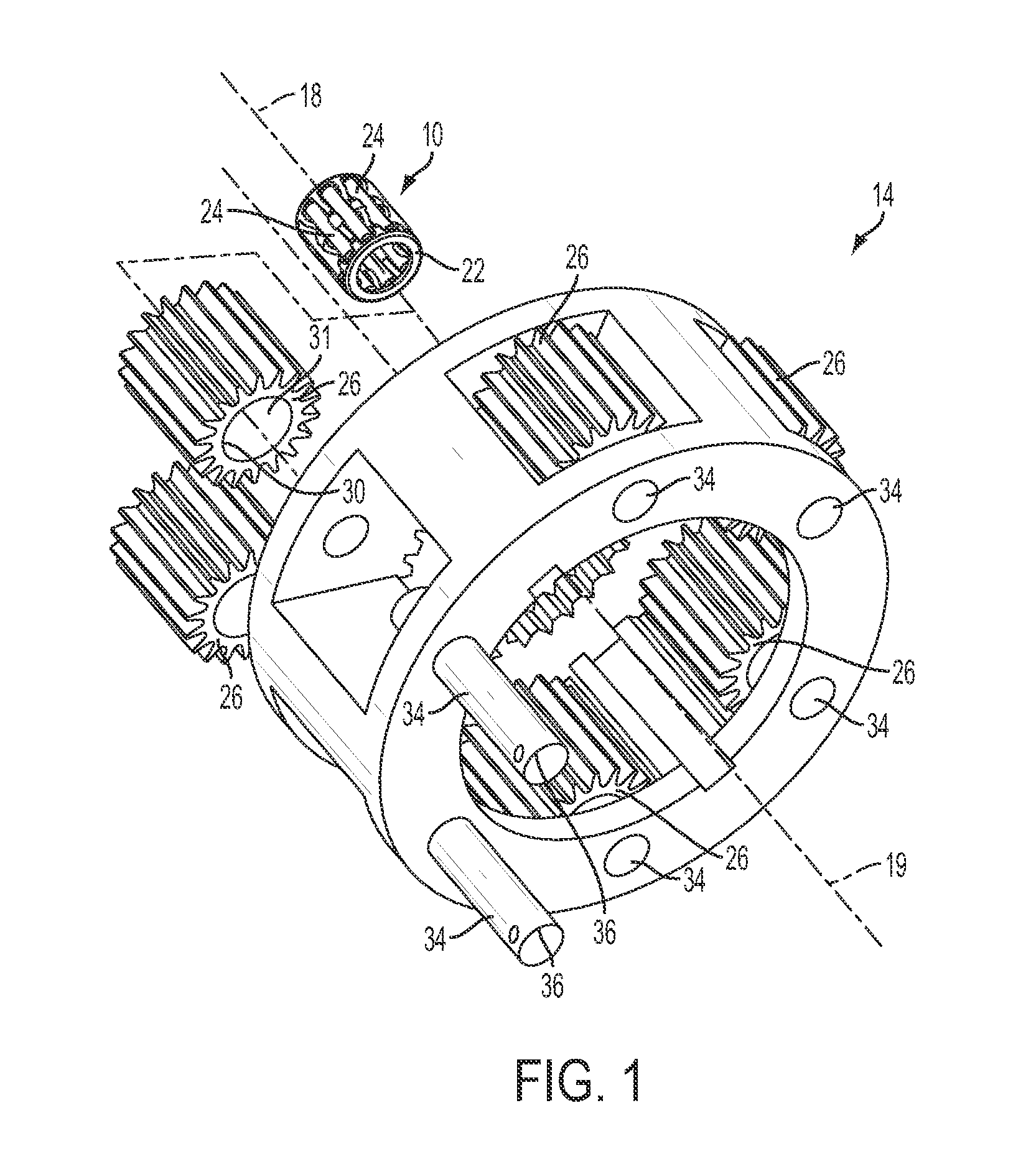
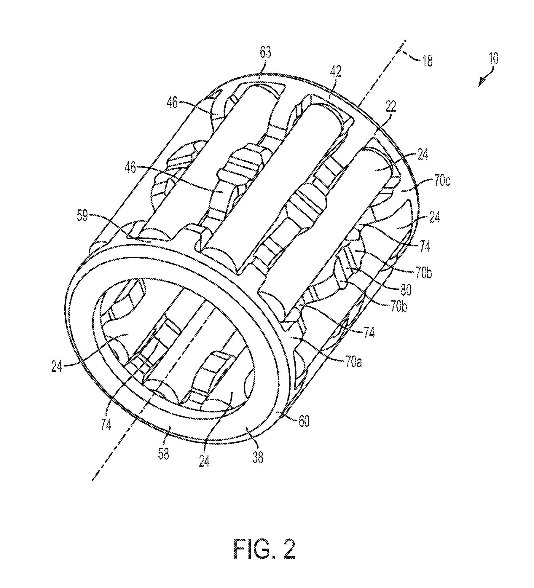
[0019]FIGS. 1 and 2 illustrate a bearing assembly 10 for use in an automatic transmission planetary gear set 14. However, one skilled in the art will understand that the bearing assembly 10 can also be used in other applications. The bearing assembly 10 includes a central axis 18, a bearing cage 22 coaxial with the central axis 18, and a plurality of rolling elements 24 (e.g., needle rollers) received by and rotatable with respect to the bearing cage 22. In the illustrated embodiment, the planetary gear set 14 includes one or more planetary gears 26, each including a central bore 30 shaped to receive the bearing assembly 10. The bearing assembly 10, in return, receives a gear axle 34, coaxial with the planetary gear 26 and the central axis 18. The bearing assembly 10 permits relative rotation of the planetary gear 26 with respect to the gear axle 34 while minimizing rotational friction therebetween. During normal operation, the plurality of rolling elements 24 contact both the inner...


PUM


Abstract

A bearing cage defines an overall axial length and includes a first end portion defining a first contact surface extending at a radially-outermost diameter of the bearing cage a first axial contact length, and a second end portion spaced a distance from the first end portion and defining a second contact surface extending at the radially-outermost diameter of the bearing cage a second axial contact length. The bearing cage further includes a plurality of spanning members extending between the first and second end portions to define a spanning member axial contact length defined at the radially-outermost diameter of the bearing cage by at least one contact pad. The bearing cage produces a total contact ratio, defined as the ratio of the sum total of the first axial contact length, the second axial contact length, and the spanning member axial contact length to the overall axial length, of at least 0.380.

Description

CLAIM OF PRIORITY[0001]This application claims priority to U.S. Provisional Application No. 61 / 186,997, filed Jun. 15, 2009, the entire disclosure of which is incorporated by reference herein.FIELD OF THE INVENTION[0002]The present invention relates to bearing cages, and more particularly to bearing cages with improved PV (Pressure×Velocity) capabilities.BACKGROUND OF THE INVENTION[0003]Bearings are commonly used whenever two contacting parts rotate with respect to one another, such as in automatic transmissions and planetary gear sets. During part assembly, handling individual rolling elements is cumbersome and time consuming. To combat these issues, rolling elements are installed into bearing cages to produce a lightweight, easy to manipulate assembly able to simplify rolling element installation and maintain equal rolling element spacing during part assembly and operation.[0004]Once installed, normal operation of a planetary gear set causes a bearing assembly to rotate simultaneo...

Claims


Application Information

Patent Timeline
IPC IPC(8): F16C33/48
CPCF16C19/46F16C33/546F16C2361/61F16C2240/40F16C33/6681F16C33/4676F16C19/463F16C33/543
Inventor BROWN, MICHAEL G.ZINKEN, GUNTER J.KLEIS, JEAN E.
Owner KOYO BEARINGS NORTH AMERICA LLC
Why Eureka
Try Eureka