Rotatable tool for chip removing machining as well as a loose top therefor

a technology of rotating tools and loose tops, which is applied in the direction of manufacturing tools, wrenches, wood boring tools, etc., can solve the problems of cumbersome mounting and dismounting of loose tops, and achieve the effect of simple and smooth axial locking

Active Publication Date: 2010-12-23
SANDVIK INTELLECTUAL PROPERTY AB
View PDF5 Cites 34 Cited by
  • Summary
  • Abstract
  • Description
  • Claims
  • Application Information

AI Technical Summary

Problems solved by technology

The concurrent requirements of fit not only between the center pin and the hole, but also between the drivers and the coupling part, impose extreme, not to say practically unattainable, requirements of manufacturing precision, and if high accuracy peradventure would be achieved, the mounting and dismounting of the loose top will become particularly cumbersome.

Method used


Image

  • Rotatable tool for chip removing machining as well as a loose top therefor
  • Rotatable tool for chip removing machining as well as a loose top therefor
  • Rotatable tool for chip removing machining as well as a loose top therefor

Examples


Embodiment Construction

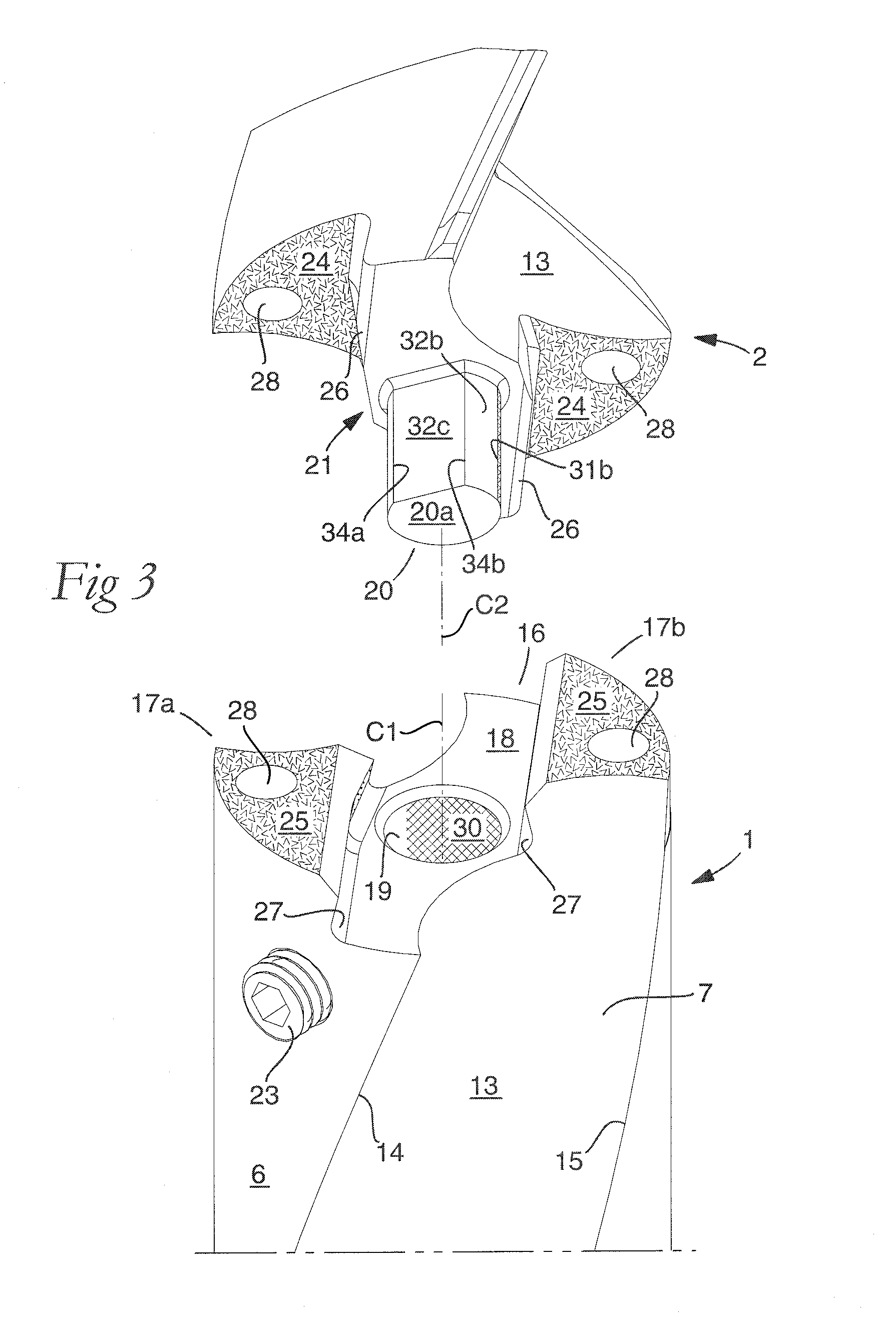
[0024]In the following, a number of co-operating pairs of surfaces of the basic body and the loose top, respectively, will be described. When these surfaces are present on the basic body, the same are denominated “support surfaces”, while the corresponding surfaces of the loose top are denominated “contact surfaces” (e.g., “axial support surface” and “axial contact surface”, respectively).

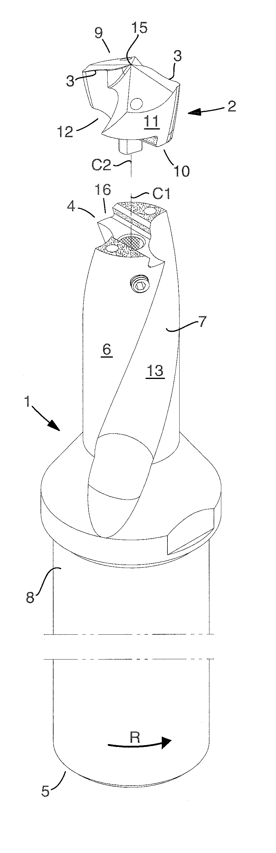
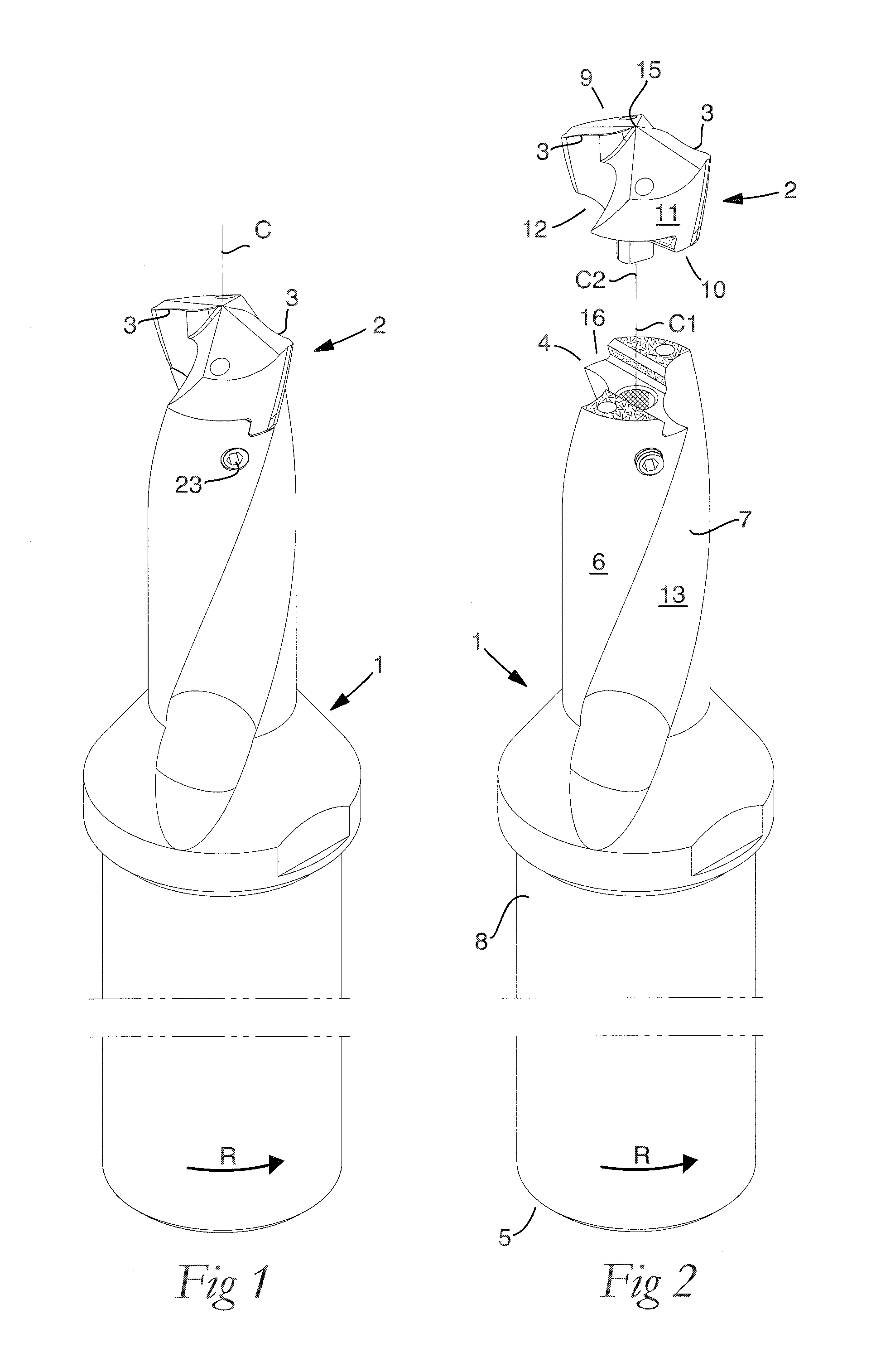
[0025]In the drawings, the invention has been exemplified in the form of two drilling tools, more precisely in the form of twist drills, i.e., drills, the chip flutes of which are helicoidal. The tool shown in FIGS. 1 and 2 includes a basic body 1 and a loose top 2 in which the requisite cutting edges 3 are included. In its assembled, operative state according to FIG. 1, the tool is rotatable around a center axis designated C, more precisely in the direction of rotation R. In FIG. 2, it is seen that the basic body 1 includes front and rear ends 4, 5 between which a center axis C1 specific to the ba...


PUM

PropertyMeasurementUnit
arc angleaaaaaaaaaa
angleaaaaaaaaaa
angle f3aaaaaaaaaa

Abstract

A rotatable tool for chip removing machining, including a basic body having front and rear ends between which a first center axis (C1) extends around which the basic body is rotatable, and a loose top having front and rear ends between which a second center axis (C2) extends. The front end of the basic body includes a jaw which is delimited by two torque-transferring drivers and an intermediate bottom in which a part of the loose top is receivable, and a center hole that mouths in the bottom of the jaw and has a hole wall which extends axially inside the basic body and in which a threaded hole mouths for a screw to co-operate with a centering pin that protrudes axially rearward from the loose top, the centering pin being insertable into the center hole. The centering pin has a cross-sectional area that is less than a cross-sectional area of the center hole. The centering pin includes two diametrically opposed surfaces, a first one of the surfaces forming a contact surface that extends tangentially between two axially running boundary generatrices which are situated along an imaginary circumscribed circle (S1), the center of which coincides with the center axis (C2) of the loose top, and between which an arc angle (α) is less than 180°. The contact surface, via the boundary generatrices, transforms into a second one of the surfaces that is spaced-apart inwardly from the circumscribed circle (S1).

Description

[0001]This application claims priority under 35 U.S.C. §119 to Swedish Patent Application No. 0900844-2, filed on Jun. 23, 2009, which is incorporated by reference herein in its entirety.FIELD OF THE INVENTION[0002]The present invention relates generally to a rotatable tool for chip removing machining and of the type that includes, on one hand, a basic body having front and rear ends, between which a first center axis extends around which the basic body is rotatable, and, on the other hand, a loose top that includes front and rear ends between which a second center axis extends, the front end of the basic body including a jaw, which is delimited by two torque-transferring drivers and an intermediate bottom and in which a part of the loose top is receivable, and a centering pin that protrudes axially rearward from the loose top being insertable into a center hole that mouths in the bottom of the jaw and has a hole wall, which extends axially inside the basic body and in which a threa...

Claims


Application Information

Patent Timeline
Patent Type & Authority Applications(United States)
IPC IPC(8): B23B31/00
CPCB23B51/02B23B2251/02Y10T408/9097Y10T408/90993Y10T408/907B23B2251/50B23B27/16B23B27/22B23B51/00B23C5/22B23B51/0003B23B51/0005B23B51/0004
Inventor AARE, MAGNUS
Owner SANDVIK INTELLECTUAL PROPERTY AB
Why Eureka
Try Eureka