Method for mechanical stoking in firing installations and firing installation

a technology of mechanical stoking and firing plant, which is applied in the direction of combustion process, lump/pulverulent fuel feeder/distribution, grates, etc., can solve the problems of not being able to comply with provisions and no longer being able to burn completely before being discharged, so as to reduce the residual carbon content of ash, reduce the rotational speed of the thrower wheel, and increase the length of the trajectory

Inactive Publication Date: 2010-12-23
SIEMENS AG OESTERR
View PDF16 Cites 5 Cited by
  • Summary
  • Abstract
  • Description
  • Claims
  • Application Information

AI Technical Summary

Benefits of technology

[0009]By virtue of the fact that the mechanical spreader stoker is offset from the end of the grate in the direction of the trajectory it is no longer possible for fresh fuel to reach the last section of the grate before the discharge, but instead only the fuel already in the process of combustion is burned completely. As a result a more complete combustion of the fuel is achieved, thereby bringing about a reduction in the residual carbon content of the ash.
[0010]By virtue of the fact that in addition the mechanical spreader stoker is disposed at a higher level a greater length of trajectory can be achieved at the same rotational speed of the thrower wheel or, alternatively, if the length of trajectory remains the same, the rotational speed of the thrower wheel can be reduced.

Problems solved by technology

The arrangement of the mechanical spreader stoker over the end of the grate has the disadvantage that fresh fuel also lands on the grate close to the end of the grate and so is no longer able to burn completely before being discharged.
This means that it may not be possible to comply with provisions governing the maximum permissible residual carbon content of the ash.

Method used


Image

  • Method for mechanical stoking in firing installations and firing installation
  • Method for mechanical stoking in firing installations and firing installation

Examples


Embodiment Construction

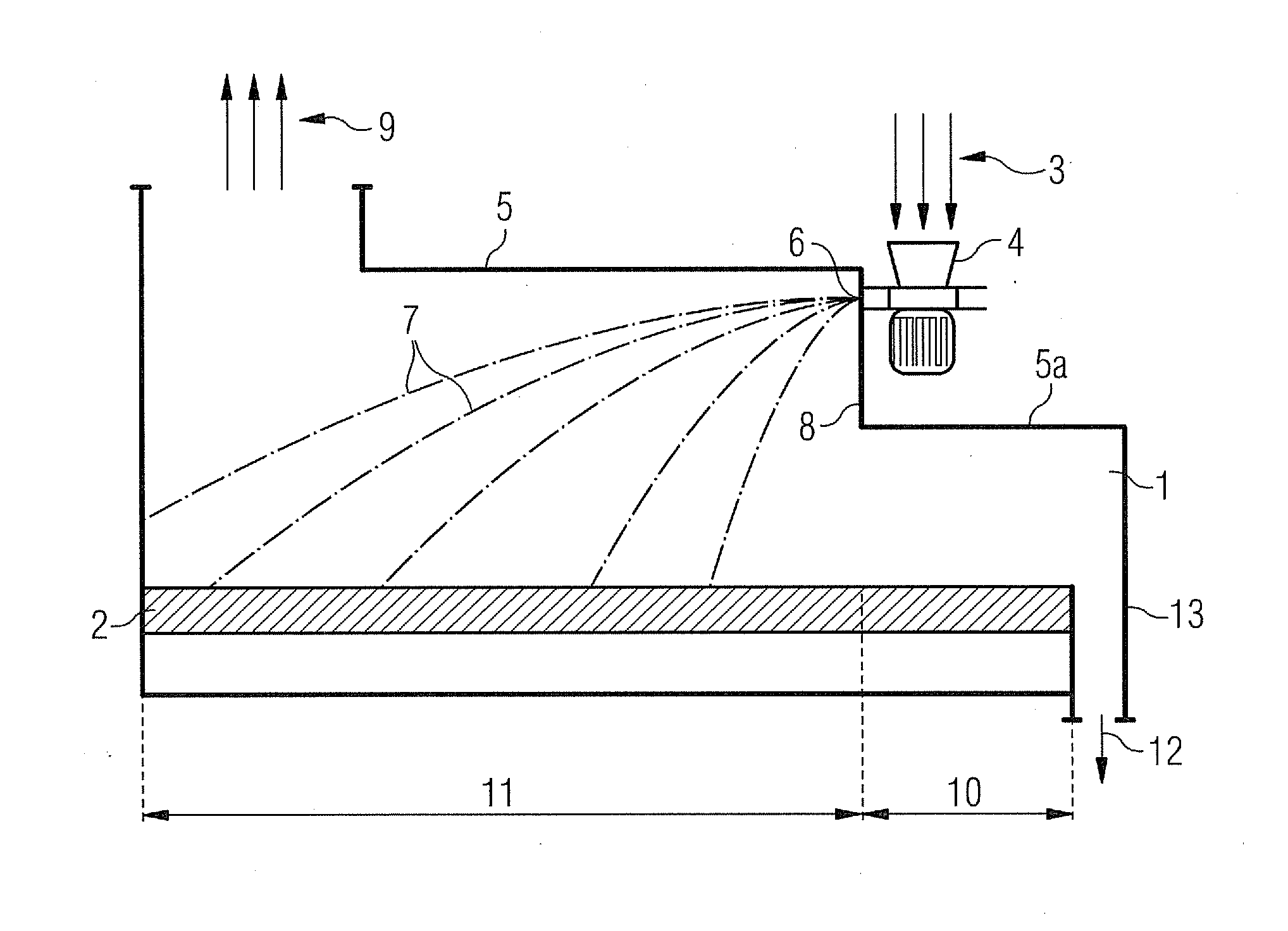
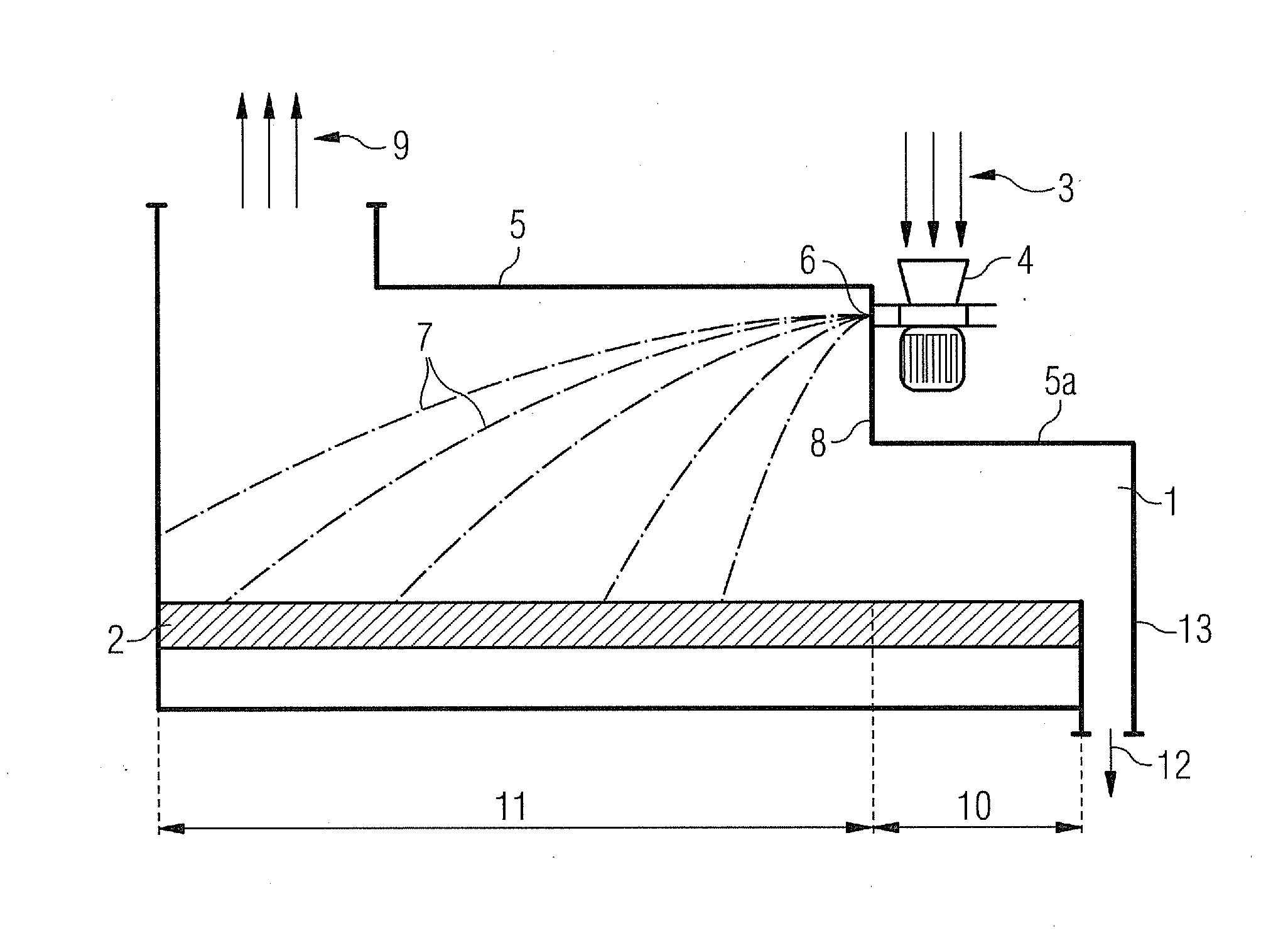
[0022]The figure schematically shows the combustion chamber 1 of a firing plant in which a grate 2 which conveys from left to right is disposed horizontally. Said forward-acting reciprocating grate consists of individual elements having bars oriented in the direction of conveyance (in this example the bars have a length of 500 mm), with only every second element being moved back and forth. The fuel 3 is supplied from above to a mechanical spreader stoker 4 and conveyed by means of the latter into the combustion chamber 1.

[0023]The mechanical spreader stoker 4 has a horizontally disposed thrower wheel, i.e. the axis of rotation of the thrower wheel is vertical. The fuel 3 is introduced into the mechanical spreader stoker 4 from above in the region of the hub of the thrower wheel and then conveyed horizontally outward with the aid of the blades of the thrower wheel and delivered—through openings in the mechanical spreader stoker—into the combustion chamber. As already mentioned previo...


PUM


Abstract

A method for mechanical stoking in firing installations and a firing installation is provided. Fuel is applied to a grate using a mechanical stoker, the grate being disposed in a firing chamber, wherein the mechanical stoker is oriented opposite a delivery direction of the grate. The fuel is introduced directly below a firing chamber ceiling, viewed in the delivery direction of the grate before the end of the grate such that a burnout zone, which does not have fresh fuel applied thereto, is created on the grate between the mechanical stoker and the end of the grate.

Description

CROSS REFERENCE TO RELATED APPLICATIONS[0001]This application is the US National Stage of International Application No. PCT / EP2009 / 051623 filed Feb. 12, 2009, and claims the benefit thereof. The International Application claims the benefit of German Application No. 10 2008 010 235.0 DE filed Feb. 21, 2008. All of the applications are incorporated by reference herein in their entirety.FIELD OF INVENTION[0002]The invention relates to a method for mechanical stoking in firing plants in which fuel is deposited by means of a mechanical spreader stoker onto a grate which is disposed in the combustion chamber, wherein the direction of throw is oriented opposite to the conveying direction of the grate, as well as to a corresponding firing plant.BACKGROUND OF INVENTION[0003]The invention can be used in firing plants employing thrower wheel mechanical stoking. In said applications the solid, particulate fuel is introduced into the combustion chamber with the aid of the thrower wheel disposed ...

Claims


Application Information

Patent Timeline
Patent Type & Authority Applications(United States)
IPC IPC(8): F23B40/02F23B30/06F23H11/00
CPCF23K3/18F23B40/02
Inventor BAUMANN, DIETMARMADLSPERGER, WOLFGANGWEISS, WILLIBALD
Owner SIEMENS AG OESTERR
Why Eureka
Try Eureka