Methods, apparatus and systems for production, collection, handling, and imaging of tissue sections
What is AI technical title?
AI technical title is built by Patsnap AI team. It summarizes the technical point description of the patent document.
a tissue section and processing method technology, applied in biochemistry apparatus and processes, instruments, artificial cells, etc., can solve the problems of inability to address the tissue collection and processing process, current “automated microtome” designs still require manual slice retrieval and manual slide or grid mounting for imaging, and retrieval necessitates skilled, delicate and incredibly time-consuming work
Active Publication Date: 2010-12-23
HAYWORTH KENNETH +1
View PDF6 Cites 12 Cited by
Summary
Abstract
Description
Claims
Application Information
AI Technical Summary
This helps you quickly interpret patents by identifying the three key elements:
Problems solved by technology
Method used
Benefits of technology
Benefits of technology
[0019]Such TEM-ready composite tape-sandwiches are designed to be mounted on reels within an “electron tomography tape cassette”, a related invention disclosed herein. This tape cassette is hermetically sealed and is designed to allow direct coupling to a standard TEM's specimen port sharing its vacuum. Any tissue section of the composite tape-sandwich can thus be reeled into the electron beam of the TEM much like the film in a movie projector. This allows for random-access imaging of any section on the tape (each tape perhaps containing tens of thousands of serial sections representing an equivalent of several cubic millimeters of brain volume) all without requiring the vacuum seal on the TEM to be broken. Cassettes include tape drive motors, positioning clamps and motors, and a precision tomographic tilt motor for 3D electron tomography. This combined system of the automatic taping lathe-microtome, the TEM-ready composite tape-sandwich, and the electron tomography tape cassette is intended to make possible the efficient creation of synapse-resolution brain connectivity atlases for the neuroscience research community.
Problems solved by technology
We are unaware of any current microtome design (either in production or disclosed in the open literature) that adequately addresses this need for automating the production, collection, handling, and imaging of large numbers of thin tissue sections suitable for use in light and transmission electron microscopic 3D reconstruction work.
Although there is a vast number of patents pertaining to microtomes and their automation, these designs are targeted toward automating the slicing process only, and do not address the tissue collection and handling processes.
Thus, current “automated microtome” designs still require manual slice retrieval and manual slide or grid mounting for imaging.
Such manual slice retrieval necessitates skilled, delicate, and incredibly time-consuming work be expended on each tissue slice (or small series of slices) as it involves “fishing” each tissue slice out of a water boat attached to the knife of the ultramicrotome instrument and onto a TEM grid.
For example, a key disadvantage of Bolles' design is that it makes no modification to the current standard microtome design which involves a discontinuous ratcheting motion of the flat block across the knife.
This seems difficult to automate reliably especially for very thin tissue slices as would be required for most neural reconstruction work.
That design also makes no modification to the current standard microtome design, and thus also suffers from the discontinuous ratcheting action.
The tape in Bolles' design and the glass slide in the Voneiff and Gibson design are much too thick for this.
Method used
Image
Click on the blue label to locate the original text in one second.
Reading with bidirectional positioning of images and text.
Examples
Embodiment Construction
[0126]In the following description of the preferred embodiment, reference is made to the accompanying drawings which form a part hereof, and in which is shown by way of illustration a specific embodiment in which the invention may be practiced. It is to be understood that other embodiments may be utilized and structural changes may be made without departing from the scope of the present invention.
Overview
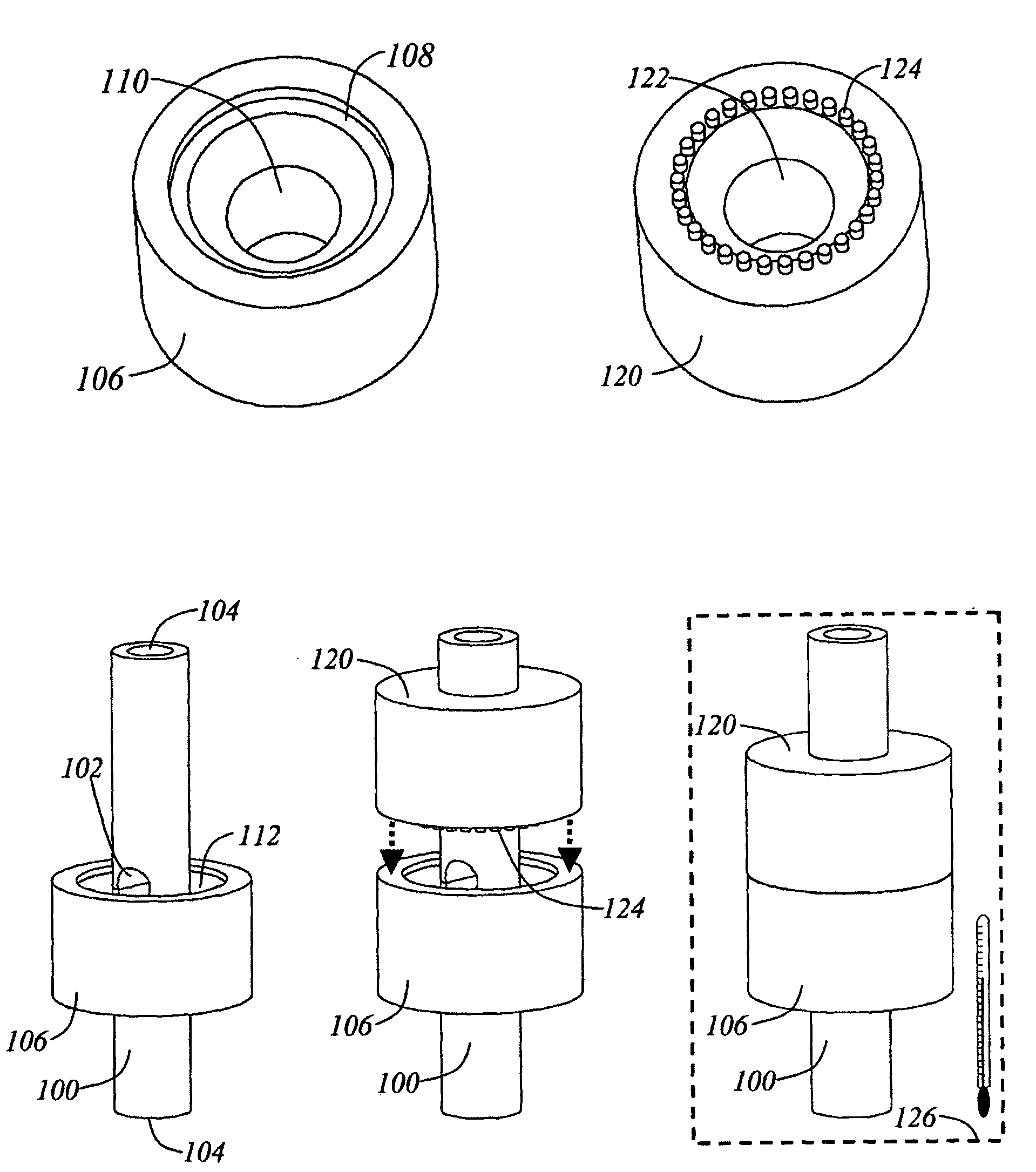
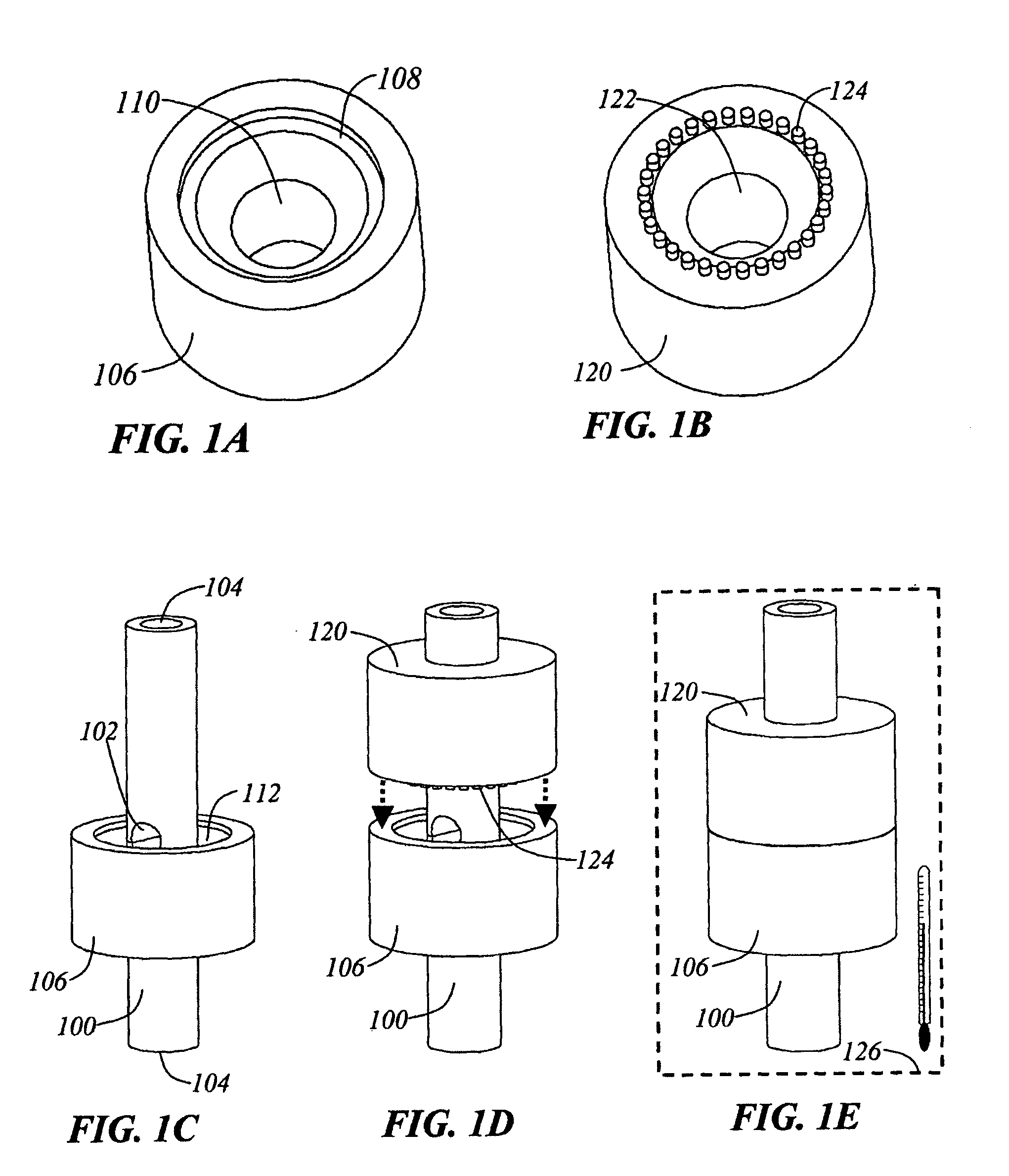
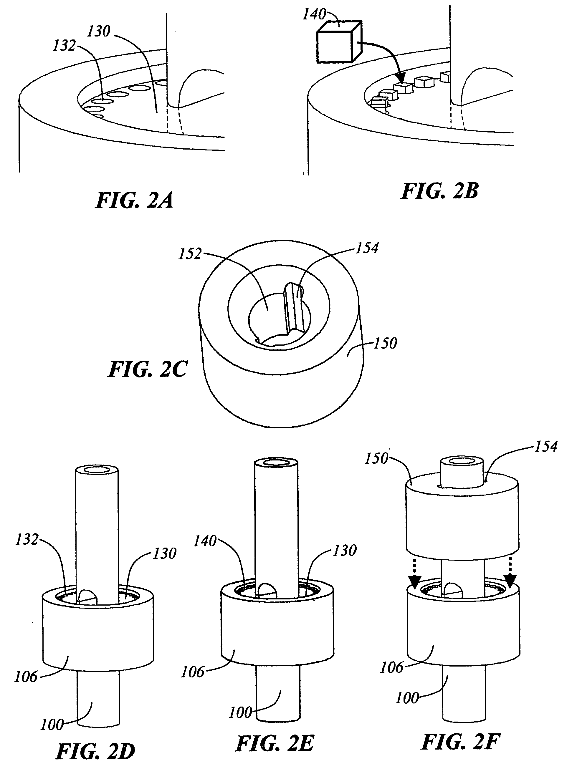
[0127]The present invention discloses a device, an automated taping lathe-microtome, and a set of associated methods and apparatuses for fully automating the collection, handling, and imaging of large numbers of serial tissue sections. In order to most clearly describe these methods and apparatuses I will first briefly outline the current method of producing serial tissue sections for TEM (transmission electron microscopic) imaging.
Current State-of-the-Art
[0128]Classical TEM tissue processing and imaging methods begin by embedding an approximately 1 mm3 piece of biological tissue th...
PUM
Abstract
Methods, apparatus and systems for collecting thin tissue samples for imaging. Thin tissue sections may be cut from tissue samples using a microtome-quality knife. In one example, tissue samples are mounted to a substrate that is rotated such that thin tissue sections are acquired via lathing. Collection of thin tissue sections may be facilitated by a conveyor belt. Thin tissue sections may be mounted to a thin substrate (e.g., by adhering thin tissue sections to a thin substrate via a roller mechanism) that may be imaged, for example, by an electron beam (e.g., in an electron microscope). This tissue sections may be strengthened before cutting via a blockface thinfilm deposition technique and / or a blockface taping technique. An automated reel-to-reel imaging technique may be employed for collected / mounted tissue sections to facilitate random-access imaging of tissue sections and maintaining a comprehensive library including a large volume of samples.
Description
CROSS REFERENCE TO RELATED APPLICATIONS[0001]This continuation application claims the benefit under 35 U.S.C. §120 of U.S. application Ser. No. 10 / 886,799, entitled “METHODS AND APPARATUSES FOR THE AUTOMATED PRODUCTION, COLLECTION, HANDLING, AND IMAGING OF LARGE NUMBERS OF SERIAL TISSUE SECTIONS,” filed on Jul. 8, 2004, which is hereby incorporated by reference in its entirety.REFERENCES CITED[0002]U.S. Pat. No. 3,939,019, filed Aug. 2, 1974, by John Pickett, entitled COVERING APPARATUS AND METHOD FOR FILM MOUNTED SERIAL TISSUE SECTIONS[0003]U.S. Pat. No. 4,545,831, filed Sep. 13, 1982, by Leonard Ornstein, entitled METHOD FOR TRANSFERRING A THIN TISSUE SECTION[0004]U.S. Pat. No. 5,746,855, filed Oct. 24, 1996, by Michael Bolles, entitled METHOD AND APPARATUS FOR AUTOMATIC ARCHIVAL STORAGE OF TISSUE SAMPLE SECTIONS CUT FROM A SAMPLE BLOCK[0005]U.S. Pat. No. 6,253,653, filed Jan. 29, 1999, by Roland Walter, et al., entitled DISC-MICROTOME[0006]U.S. Pat. No. 6,387,653, filed Apr. 9, 1...
Claims
Application Information
Patent Timeline
Application Date:The date an application was filed.
Publication Date:The date a patent or application was officially published.
First Publication Date:The earliest publication date of a patent with the same application number.
Issue Date:Publication date of the patent grant document.
PCT Entry Date:The Entry date of PCT National Phase.
Estimated Expiry Date:The statutory expiry date of a patent right according to the Patent Law, and it is the longest term of protection that the patent right can achieve without the termination of the patent right due to other reasons(Term extension factor has been taken into account ).
Invalid Date:Actual expiry date is based on effective date or publication date of legal transaction data of invalid patent.
Patent Type & AuthorityApplications(United States)

