Root cause analysis method, apparatus, and program for it apparatuses from which event information is not obtained

a root cause analysis and event information technology, applied in the field of system management methods, an apparatus, a system, and a program, can solve the problems of large-scale, complex and large-scale of each it system, and affect the various it apparatuses

Active Publication Date: 2010-12-23
HITACHI LTD
View PDF19 Cites 73 Cited by
  • Summary
  • Abstract
  • Description
  • Claims
  • Application Information

AI Technical Summary

Benefits of technology

[0016]According to the present invention, even when an event has occurred in an IT apparatus from which event information is not obtained, an analysis result can be displayed.

Problems solved by technology

Recent years, each IT system (IT is an abbreviation for Information Technology, and hereinafter, an IT system is also referred to as an information processing system) has become complex and large-scaled because various IT apparatuses (hereinafter, also referred to as information processing apparatuses) are coupled thereto via a network.
Faults may affect the various IT apparatuses via the network.

Method used


Image

  • Root cause analysis method, apparatus, and program for it apparatuses from which event information is not obtained
  • Root cause analysis method, apparatus, and program for it apparatuses from which event information is not obtained
  • Root cause analysis method, apparatus, and program for it apparatuses from which event information is not obtained

Examples


first embodiment

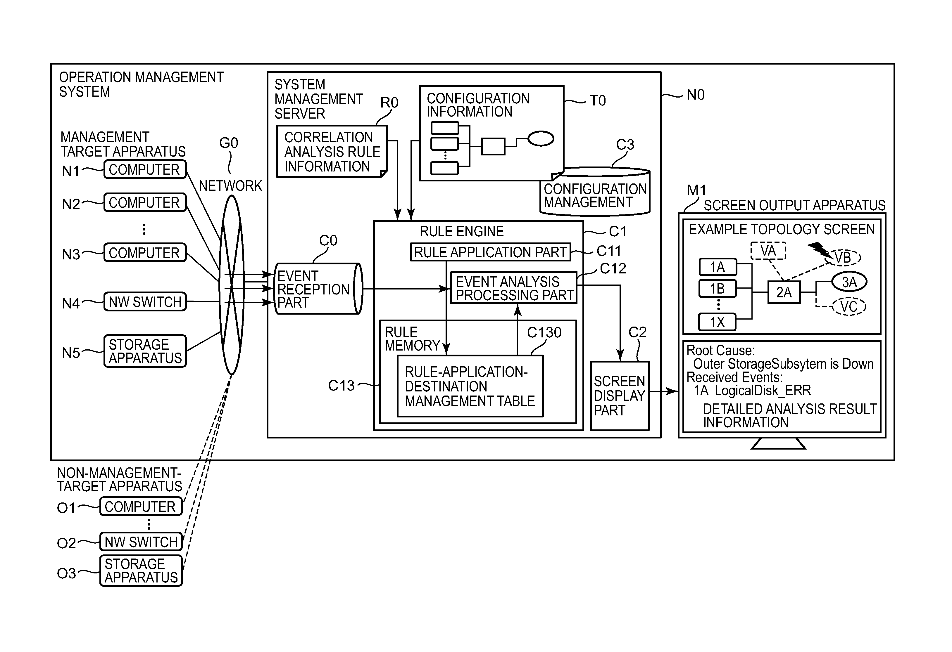
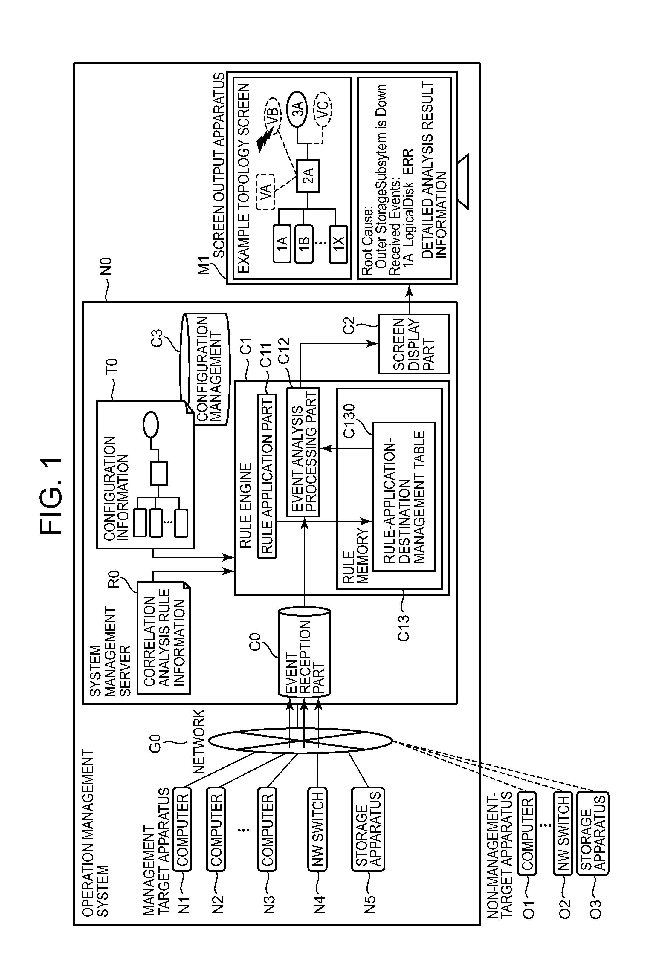
[0047]FIG. 1 is an overview showing one configuration of an information processing system for implementing the present invention.

[0048]The information processing system includes an operation management system and a system management server. In the operation management system, the system management server N0 monitors and manages, as management targets, computers, a network switch (NW switch), and a storage apparatus which constitute the IT system.

[0049]The system management server N0 of the present invention includes an event reception part C0 for receiving event information such as a status change in a management-target IT apparatus, fault information, and notification information; a rule engine C1 for performing fault analysis based on the received event information according to a rule R0 defined in advance; configuration management C3 for managing configuration information of management-target IT apparatuses; and a screen display part C2 for outputting information required for ope...

second embodiment

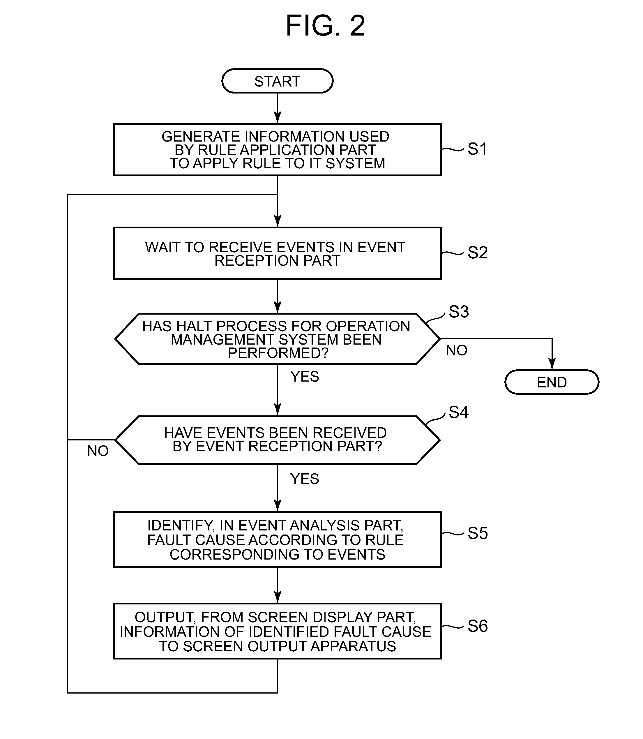
[0187]In a second embodiment of the present invention, the processing procedure of the entire fault-analysis processing flow shown in FIG. 2 in the first embodiment is performed in a manner such that Step S4b of generating application information in the rule application part C11 is performed after Step S3b of receiving events and before Step S5b of event analysis processing performed in the event analysis part C12, as shown in FIG. 20.

[0188]The only difference between the first embodiment and the second embodiment is the timing of generating rule application information.

[0189]As described above, even when the timing for rule application information is changed and the present invention is implemented, the advantages are still provided and a message indicating that a non-management-target IT apparatus is the root cause apparatus of a fault can be displayed on the screen.

[0190]According to the first and second embodiments, described in the specification of this application, a program t...


PUM


Abstract

In the system management server, an information processing apparatus that is an event-information acquisition target is registered as a monitored apparatus in configuration information; event information that complies with a rule stored in advance is identified from among a plurality of pieces of event information stored in the system management server; a server apparatus for a network service related to the event information is identified; and a message is displayed which indicates that the cause of the event that occurred in a client information processing apparatus which has generated event information is an event related to the network service, which occurred in the server apparatus.

Description

TECHNICAL FIELD[0001]A technology disclosed in this specification relates to a system management method, an apparatus, a system, and a program for managing an operation of an information processing system which includes a server computer, a network apparatus, and a storage apparatus, and to a medium that includes the program, and an apparatus for delivering the program.BACKGROUND ART[0002]Recent years, each IT system (IT is an abbreviation for Information Technology, and hereinafter, an IT system is also referred to as an information processing system) has become complex and large-scaled because various IT apparatuses (hereinafter, also referred to as information processing apparatuses) are coupled thereto via a network. Faults may affect the various IT apparatuses via the network. As an example of root cause analysis technologies of identifying the locations and causes of the faults, Patent Document 1 discloses an event correlation technology of analyzing a fault location and a cau...

Claims


Application Information

Patent Timeline
Patent Type & Authority Applications(United States)
IPC IPC(8): G06F11/34
CPCG06F11/0709G06F11/079G06F11/3476G06F11/3495G06F2201/86G06F11/3452H04L41/0631H04L41/16H04L61/1511H04L67/1097H04L29/12066H04L61/4511
Inventor MORIMURA, TOMOHIRONAGAI, TAKAYUKISUGAUCHI, KIMINORIKURODA, TAKAKIARATO, YOSHIHIRO
Owner HITACHI LTD
Why Eureka
Try Eureka