Television schedule system

a schedule system and television technology, applied in the field of television schedule system, can solve the problems of difficult to set a vcr for automatic recording at a future date, record the wrong program or not to record anything, and make such a system and process easy and convenient to operate, and achieve the effect of simplified user control of a television and easy access

Inactive Publication Date: 2010-12-23
ALL MEDIA GUIDE +10
View PDF103 Cites 22 Cited by
  • Summary
  • Abstract
  • Description
  • Claims
  • Application Information

AI Technical Summary

Benefits of technology

[0024]According to yet another aspect of the present invention, user control of a television is simplified by a system and process that displays on a television screen, overla

Problems solved by technology

The difficulty of setting a VCR for automatic recording at a future date is notorious.
Even users who are technically sophisticated will often make mistakes in the VCR programming procedure that cause them to record the wrong program or not to record anything at all.
This difficulty has even resulted in a substantial body of humor dedicated to the subject of programming VCRs.
Such a user interface removes a great deal of the mystery from VCR programming, but users still have difficulty with such a command-based interface and encounter problems carrying out the programming without making mistakes that cause them to miss recording programs they would like to watch at a different time than when they are broadcast.
However, the provision of a highly intuitive user interface that makes such a system and process easy and convenient to operate is a difficult task.
If this array is navigated by a cursor that goes from cell to cell, a single cursor command can produce violent screen changes.
Not only is this unsettling, but may take considerable effort to recover.
When using a television set as a display for a schedule system, the size and resolution of the television display limit the amount of text that can be displayed with the grid.
Prog

Method used


Image

  • Television schedule system
  • Television schedule system
  • Television schedule system

Examples


Embodiment Construction

I. User Interface

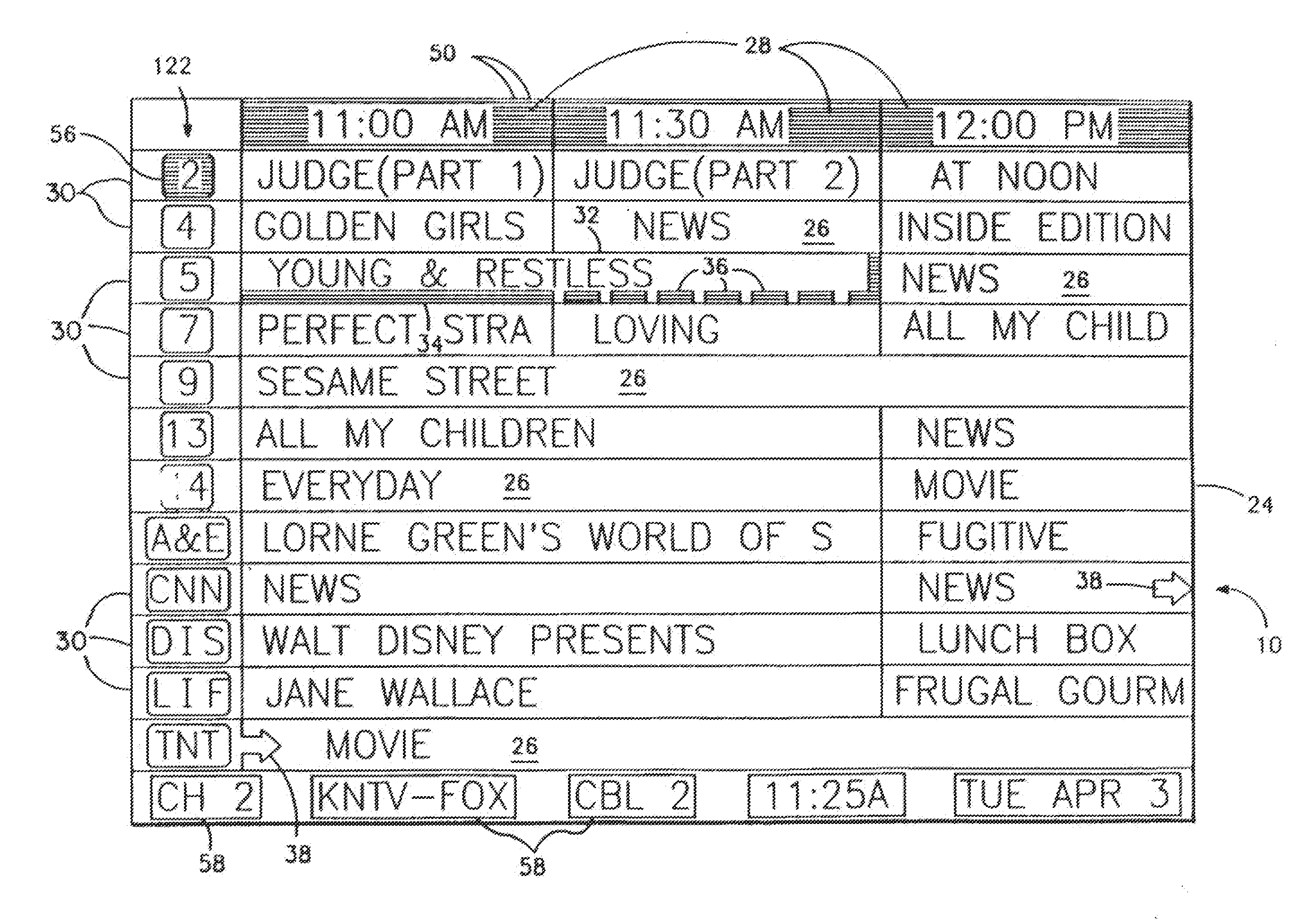
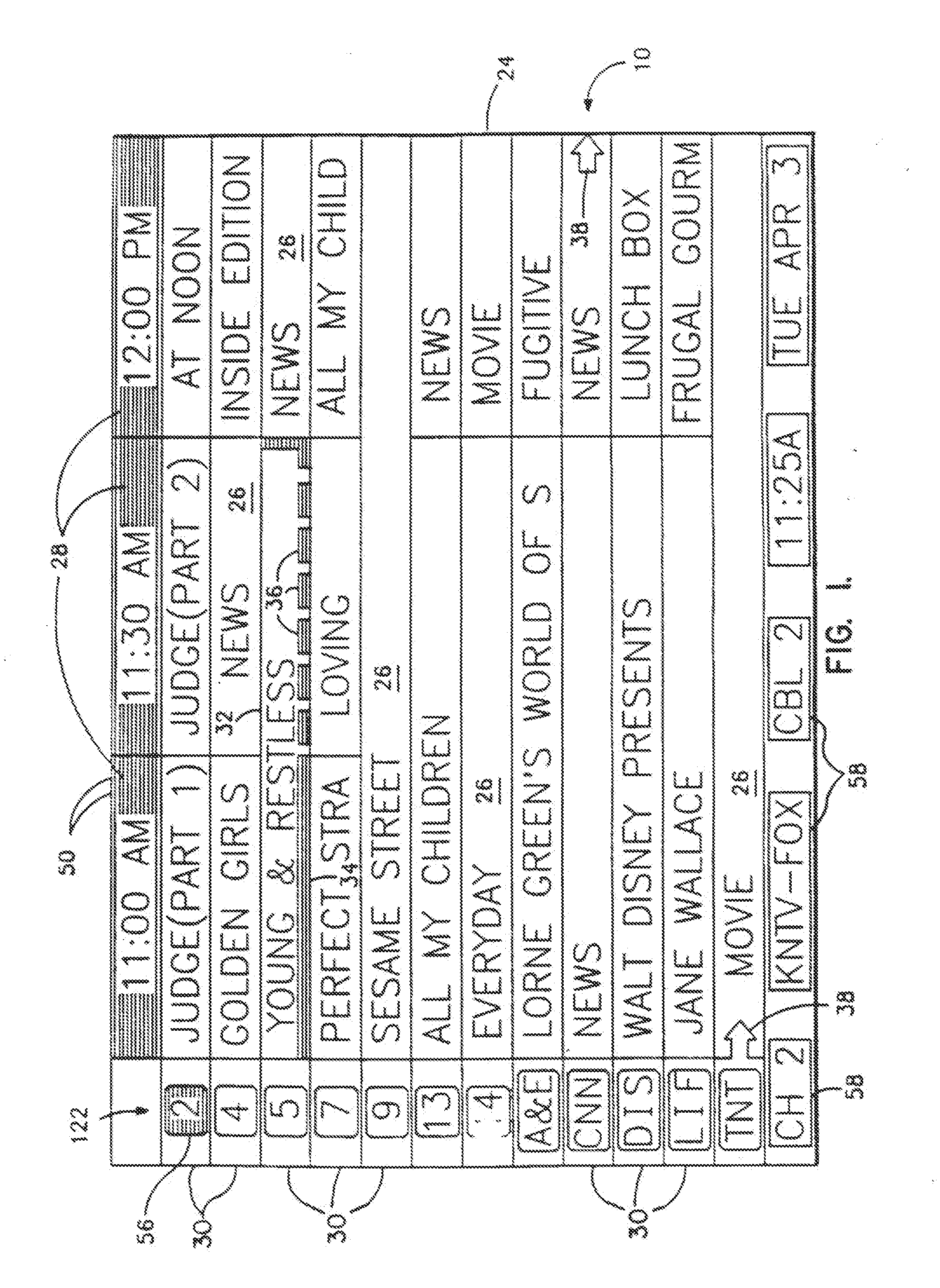
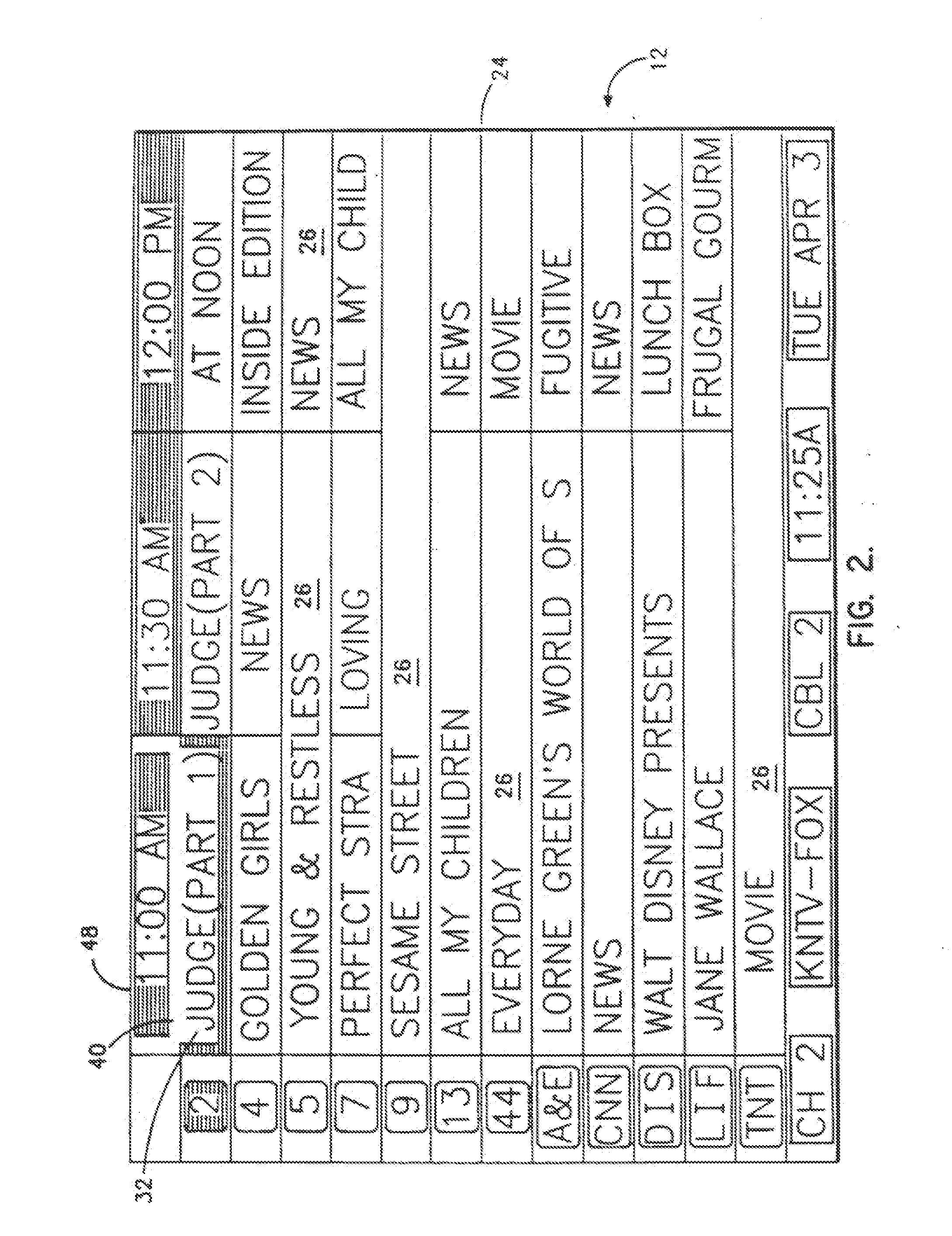
[0045]Turning now to the drawings, more particularly to FIGS. 1-7, there are shown a series of menu screens 10, 12, 14, 16, 18, 20 and 22 used in operation of the system and carrying out the process of the invention. Screens 10, 12, 14, 18 and 20 each consists of an array 24 of irregular cells 26, which vary in length, corresponding to different television program lengths of one half hour to one-and-one half hours or more. The array is arranged as three columns 28 of one-half hour in duration, and twelve rows 30 of program listings. Some of the program listings overlap two or more of the columns 28 because of their length. Because of the widely varying length of the cells 26, if a conventional cursor used to select a cell location were to simply step from one cell to another, the result would be abrupt changes in the screens 10, 12, 14, 18 and 20 as the cursor moved from a cell 26 of several hours length to an adjacent cell in the same row. Such abrupt changes disor...


PUM


Abstract

Screen (10) for a user interface of a television schedule system and process consists of an array (24) of irregular cells (26), which vary in length, corresponding to different television program lengths of one half hour to one-and-one half hours or more. The array is arranged as three columns (28) of one-half hour in duration, and twelve rows (30) of program listings. Some of the program listings overlap two or more of the column (28) because of their length. Because of the widely varying length of the cells (26), if a conventional cursor used to select a cell location were to simply step from one cell to another, the result would be abrupt changes in the screen (10) as the cursor moved from a cell (26) of several hours length to an adjacent cell in the same row. An effective way of taming the motion is to assume that behind every array (24) is an underlying array of regular cells. By restricting cursor movements to the regular cells, abrupt screen changes will be avoided. With the cursor (32), the entire cell (26) is 3-D highlighted, using a conventional offset shadow (34). The offset shadow (34) is a black bar that underlines the entire cell and wraps around the right edge of the cell. To tag the underlying position—which defines where the cursor (32) is and thus, where it will move next—portions (36) of the black bar outside the current underlying position are segmented, while the current position is painted solid.

Description

CROSS REFERENCE TO RELATED APPLICATIONS[0001]This application is a continuation of U.S. patent application Ser. No. 10 / 961,008, filed Oct. 7, 2004, which is a continuation of U.S. patent application Ser. No. 09 / 132,479, filed Aug. 11, 1998, now abandoned, which is a continuation-in-part of U.S. patent application Ser. No. 08 / 033,773, filed Mar. 19, 1993, now U.S. Pat. No. 5,353,121, which is a continuation-in-part both of U.S. patent application Ser. No. 07 / 579,555, filed Sep. 10, 1990, now abandoned, and of U.S. patent application Ser. No. 07 / 916,043, filed Jul. 17, 1992, now abandoned and which is a continuation of U.S. patent application Ser. No. 07 / 778,404, filed Oct. 17, 1991, now U.S. Pat. No. 5,151,789, which is a continuation-in-part of U.S. patent application Ser. No. 07 / 428,620, filed Oct. 30, 1989, now abandoned each of which is fully incorporated herein by reference in its respective entirety.BACKGROUND OF THE INVENTION[0002]One aspect of the present invention relates ge...

Claims


Application Information

Patent Timeline
IPC IPC(8): H04N5/445B64C30/00G04G15/00G11B15/02G11B27/10G11B27/11G11B27/30G11B27/32G11B27/34G11B27/36G11B33/10H04N5/44H04N5/765H04N5/775H04N5/782H04N7/025H04N7/088H04N7/10H04N7/16
CPCG04G15/006H04N2005/4423G11B27/107G11B27/11G11B27/3054G11B27/324G11B27/328G11B27/34G11B27/36G11B2220/41G11B2220/65G11B2220/80G11B2220/90H04N5/445H04N5/44504H04N5/44543H04N5/765H04N5/775H04N5/782H04N7/0884H04N7/163H04N7/165H04N21/235H04N21/4135H04N21/42204H04N21/4314H04N21/4316H04N21/4334H04N21/4335H04N21/435H04N21/43622H04N21/47H04N21/47214H04N21/482H04N21/4821H04N21/4828H04N21/485H04N21/4858H04N21/4882H04N21/6118H04N21/8186H04N21/84H04N21/858G11B27/10H04N21/41265
Inventor YOUNG, PATRICKROOP, JOHN H.FABER, MICHAEL W.
Owner ALL MEDIA GUIDE
Why Eureka
Try Eureka