Examination bed movement device

Inactive Publication Date: 2010-12-30
SIEMENS AG
View PDF3 Cites 2 Cited by
  • Summary
  • Abstract
  • Description
  • Claims
  • Application Information

AI Technical Summary

Benefits of technology

[0011]The present embodiments may be used for beds of an MR system or CT system, for example. The examination bed horizontal movement device of the present embodiments enables the design of a compact horizontal structure of an examination bed for a strong magnetic field (e.g., ≧1.5 T) MRI system or CT system and is capable of highly repeatable positioning accuracy (e.g., no more than 0.5 mm) of the horizontal movement, without limiting the d

Problems solved by technology

However, the horizontal movement of the examination bed is limited by the structure of the examination bed.
This brings about a limitation to the design of the backbone coil

Method used


Image

  • Examination bed movement device
  • Examination bed movement device
  • Examination bed movement device

Examples


Example

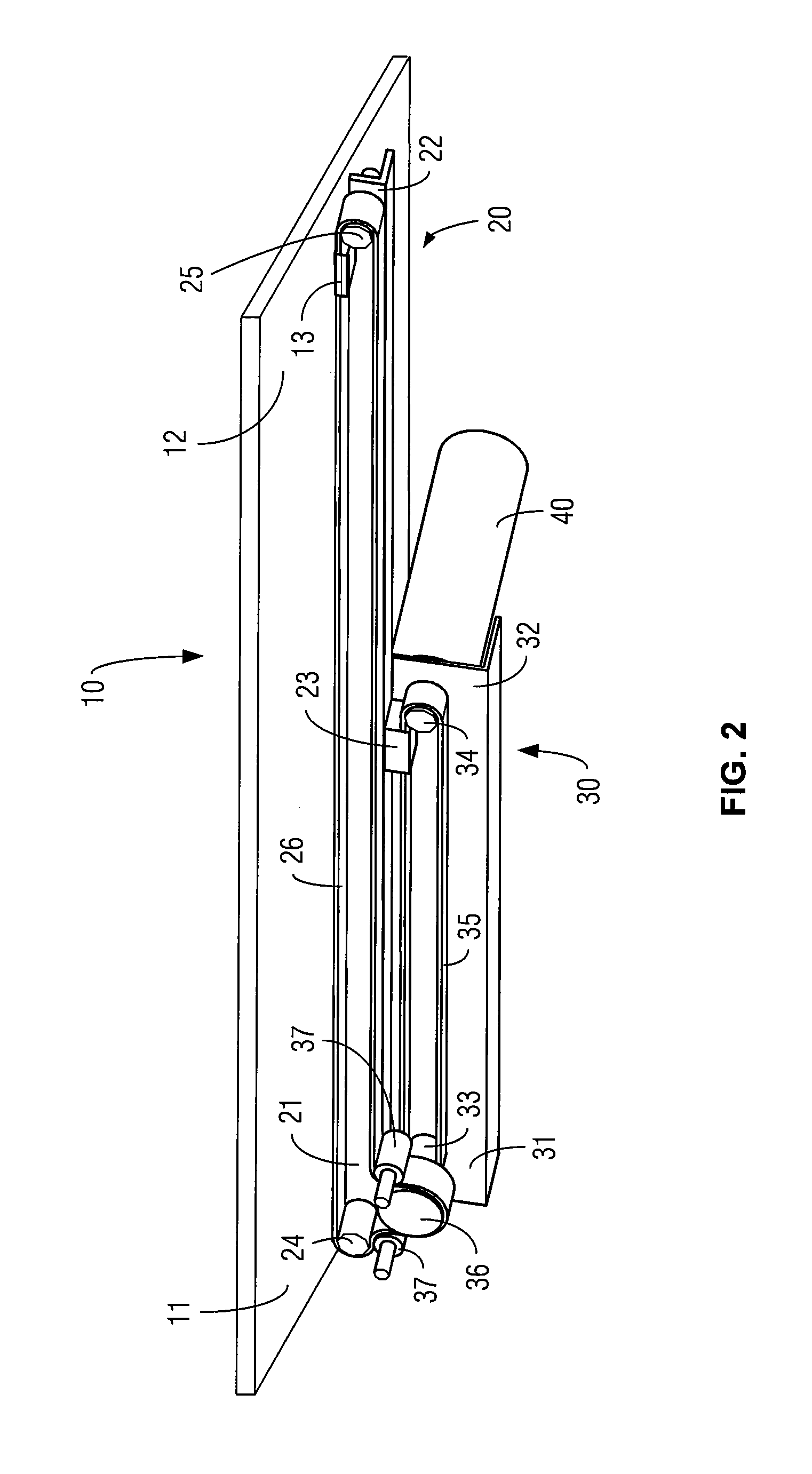
DETAILED DESCRIPTION OF THE DRAWINGS

[0015]The present embodiments are described below in conjunction with the drawings in order to further clarify the technical features, purpose and effect of the present embodiments. The same number represents the same part shown in the drawings. In order to clarify the structure and interrelation of all the components, the scale of all components in the drawings are schematic only, and do not represent the scale of the real structure.

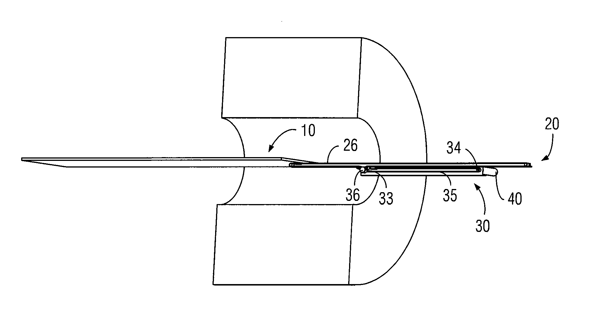
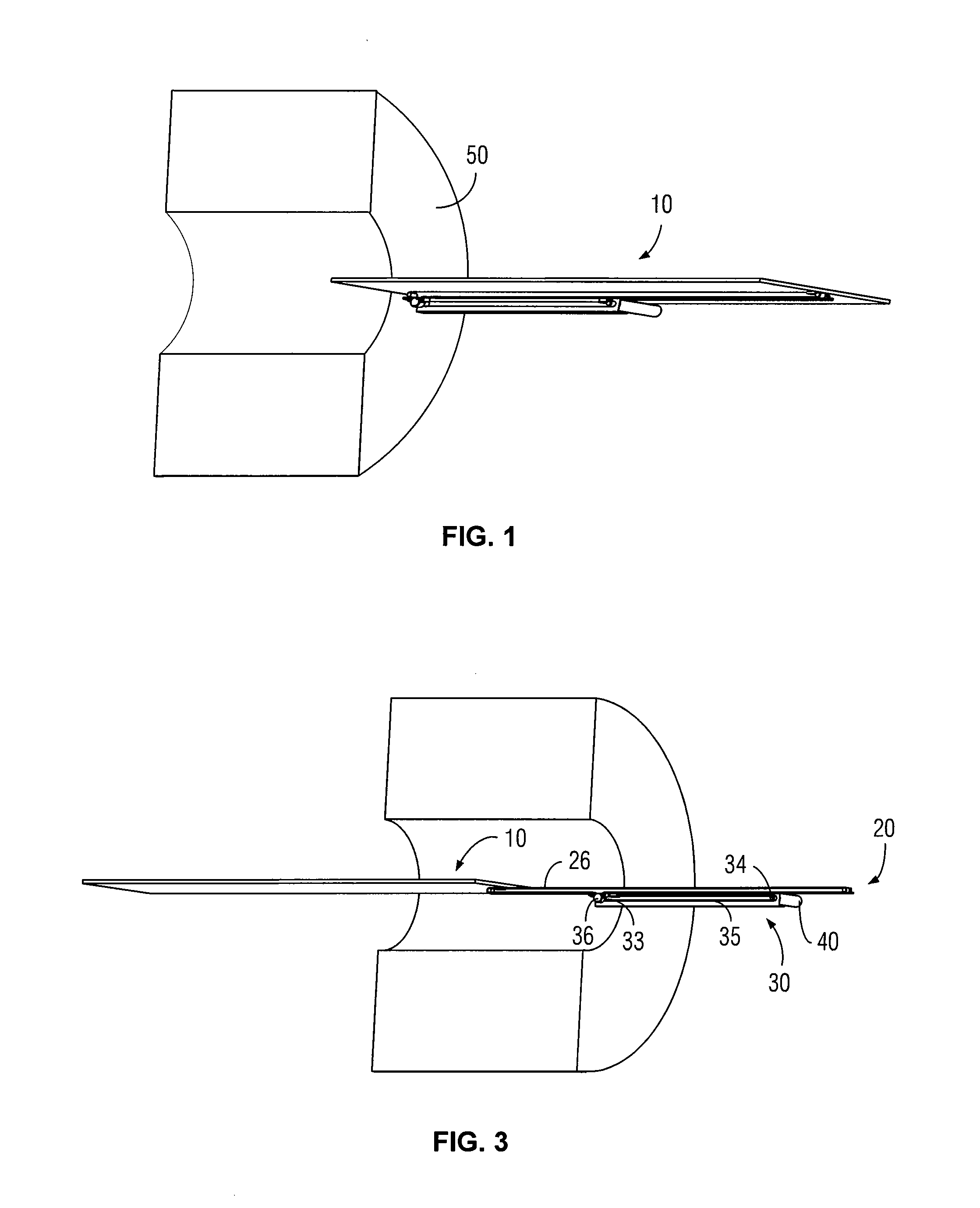
[0016]FIG. 1 shows a schematic diagram of the initial position of one embodiment of an examination bed horizontal movement device. As shown in FIG. 1, an MR system or CT system, for example, includes a magnet 50 and an examination bed 10. The subject to be examined lies on the top surface of the examination bed 10. During examination, the examination bed 10 moves horizontally, moving the part to be examined into the magnet 50. For illustration purposes, the direction that the examination bed 10 moves into the magnet 5...


PUM


Abstract

An examination bed horizontal movement device including an examination bed, an examination bed connector fixed at the bottom of the examination bed, a support board and a fixed board is provided. Two tension wheels are installed at the front and back ends of the support board separately, and the two tension wheels are connected by an examination bed conveyor belt. A tension wheel and a driving wheel are fixed at both ends of the fixed board, and the tension wheel and the driving wheel are connected by a support board conveyor belt. A driving wheel is installed coaxially on the fixed board tension wheel, and the examination bed conveyor belt winds around the driving wheel. The movement device achieves a compact design of the horizontal structure for the examination bed in a strong magnetic field MRI system and provides long travel and highly repeatable positioning accuracy of the horizontal movement.

Description

[0001]This application claims the benefit of CN 200920163228.7, filed Jun. 30, 2009, which is hereby incorporated by reference.BACKGROUND[0002]The present embodiments relate to an examination bed movement device.[0003]A whole body scanning function may be used for advanced MR systems or CT systems. For the whole body scanning function, an examination bed has long-travel horizontal movement (e.g., may reach 2800 mm), so that the whole body scanning and imaging can be completed by having the person to be examined lie on the examination bed in one posture.[0004]However, the horizontal movement of the examination bed is limited by the structure of the examination bed. In order to allow long horizontal movement, a horizontal movement device may be installed on the bottom of the examination bed. In operating conditions, the horizontal movement device can move the examination bed into the inside of the magnet or CT scanning area horizontally and can bring the examination bed back to the or...

Claims


Application Information

Patent Timeline
IPC IPC(8): A61G7/10
CPCA61B5/0555G01R33/307A61B6/0457A61B5/055A61B6/0487
Inventor LIU, JIAN
Owner SIEMENS AG
Why Eureka
Try Eureka