Campfire support unit

a technology for supporting units and firewood, which is applied in the field of campfires, can solve the problems of no mechanism for utilizing the holder to support firewood outside the holder, and achieve the effect of reducing the number of holder parts

Inactive Publication Date: 2010-12-30
DUPONT DANIEL L
View PDF35 Cites 11 Cited by
  • Summary
  • Abstract
  • Description
  • Claims
  • Application Information

AI Technical Summary

Problems solved by technology

There is no mechanism for utilizing the ho...

Method used


Image

  • Campfire support unit
  • Campfire support unit
  • Campfire support unit

Examples


Embodiment Construction

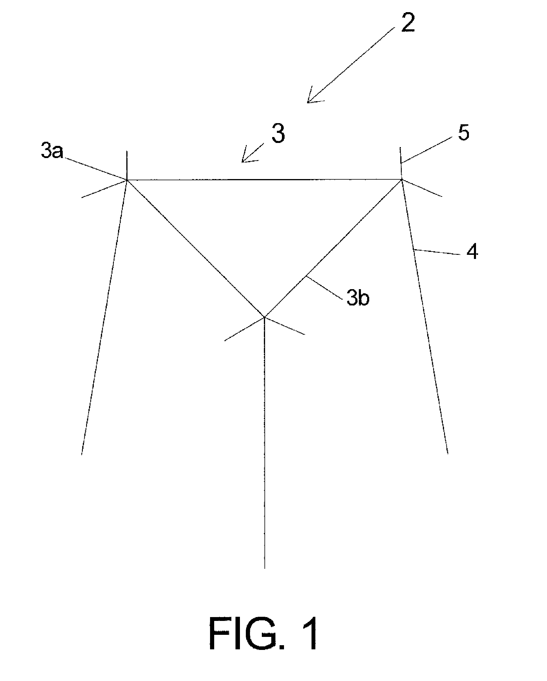
[0006]More specifically, reference is made to FIG. 1, in which is shown a first embodiment of a campfire support unit for burning firewood in a fire pit, fire ring, or on open ground, made in accordance with the principles of the present invention, and generally designated by the numeral 2.

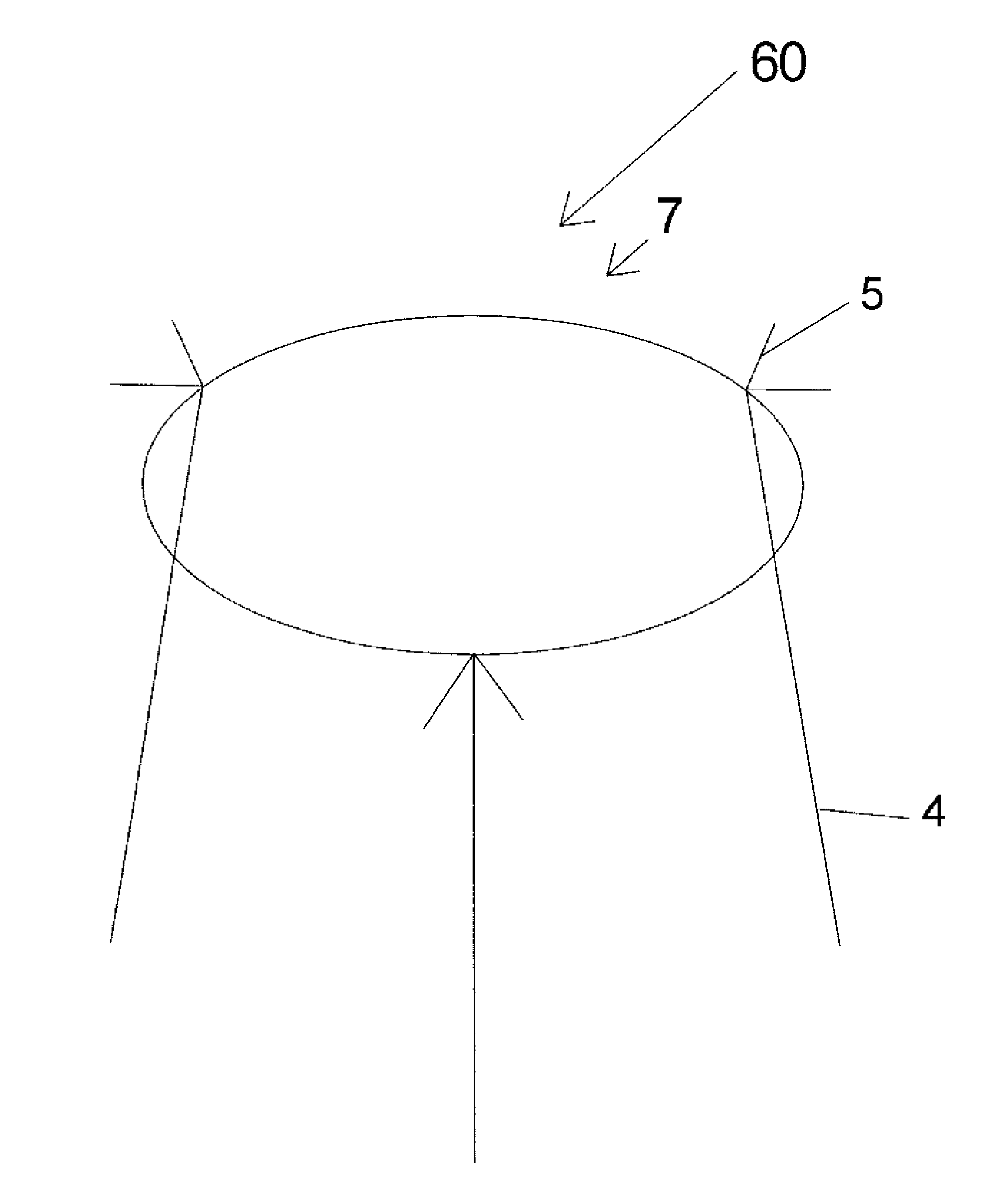
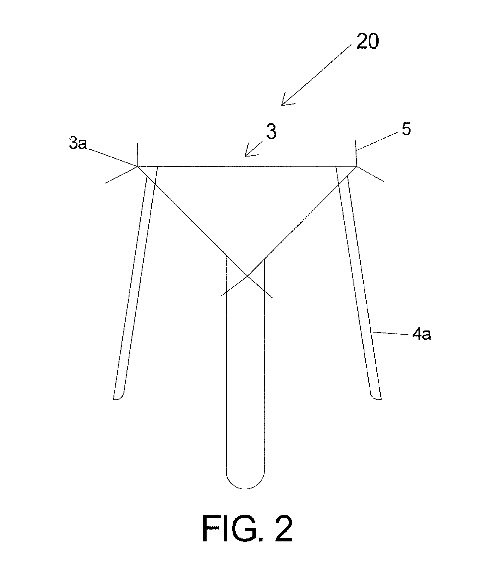
[0007]The campfire support unit 2 comprises a rigid triangular annular member 3 constructed and arranged to confine and enclose firewood (not shown). The rigid triangular annular member 3 is supported by a plurality of legs 4, each leg 4 being connected to each apex 3a of the rigid triangular annular member 3. A pair of rigid tabs 5 extends outward from each apex of the perimeter 3b of the rigid triangular annular member 3. The tabs 5 are constructed and arranged to provide lateral support for firewood disposed outside the perimeter 3b of the rigid triangular annular member 3

[0008]The campfire support unit 2 is constructed and arranged to support wood for a wood fire in a near-vertical ring orient...


PUM


Abstract

A campfire support unit for burning firewood. The unit has a metal frame that includes a metal support ring with metal tabs and support legs. The frame is made and arranged to support wood for a wood fire in a near-vertical ring position around a central core which contains wood supported in a near-vertical position. An internal core fire is started, using wood placed inside the metal ring. Then wood is leaned against the outer rim of the metal ring. The tabs support the wood leaned against the outer rim, preventing it from falling before, during, and after the outer wood is ignited by the internal core fire.

Description

BACKGROUND OF THE INVENTION[0001]The present invention relates to campfires. More particularly, the invention relates to a campfire support unit for burning firewood.[0002]U.S. Pat. No. 5,722,390 to Hannebaum discloses a fireplace wood holder which holds firewood in a vertical position, so that the firewood's fibers and water-conducting channels are oriented substantially up and down, to allow more nearly complete burning and combustion. However, the fireplace holder provides only for wood that is enclosed by the holder. There is no mechanism for utilizing the holder to support firewood external of the holder. Although the applicant was, at the time he invented his campfire unit, not aware of the patent to Hannebaum, the present invention provides such a mechanism.SUMMARY OF THE INVENTION[0003]In general, the present invention provides a campfire support unit for burning firewood. The campfire support unit comprises (a) an annular member constructed and arranged to confine enclosed ...

Claims


Application Information

Patent Timeline
IPC IPC(8): F24B1/193
CPCF24B1/193
Inventor DUPONT, DANIEL L.
Owner DUPONT DANIEL L
Why Eureka
Try Eureka