1-axis and 2-axis solar trackers

Inactive Publication Date: 2010-12-30
CHEN DATONG
View PDF0 Cites 34 Cited by
  • Summary
  • Abstract
  • Description
  • Claims
  • Application Information

AI Technical Summary

Benefits of technology

[0015]As known in the prior arts, polar tracking has advantage of simple driving and control requirement, while the rotation around the polar axis is almost at steady speed: 360 degrees per day, the declination angle change is very slow, only changes ±23½° back and forth per year. It would be a good approximation that the declination angle could be kept constant for a day. As a matter of fact, the declination angle change rate varies, its fastest change rate is less than ±0.1° for ±6 hour, while the sun itself has a ±0.267° angular size.

Problems solved by technology

Of course we have to set the next correct declination angle for the next day, a manual adjustment is tedious, a continuous adjustment is an overkill as others alre

Method used


Image

  • 1-axis and 2-axis solar trackers
  • 1-axis and 2-axis solar trackers
  • 1-axis and 2-axis solar trackers

Examples


Embodiment Construction

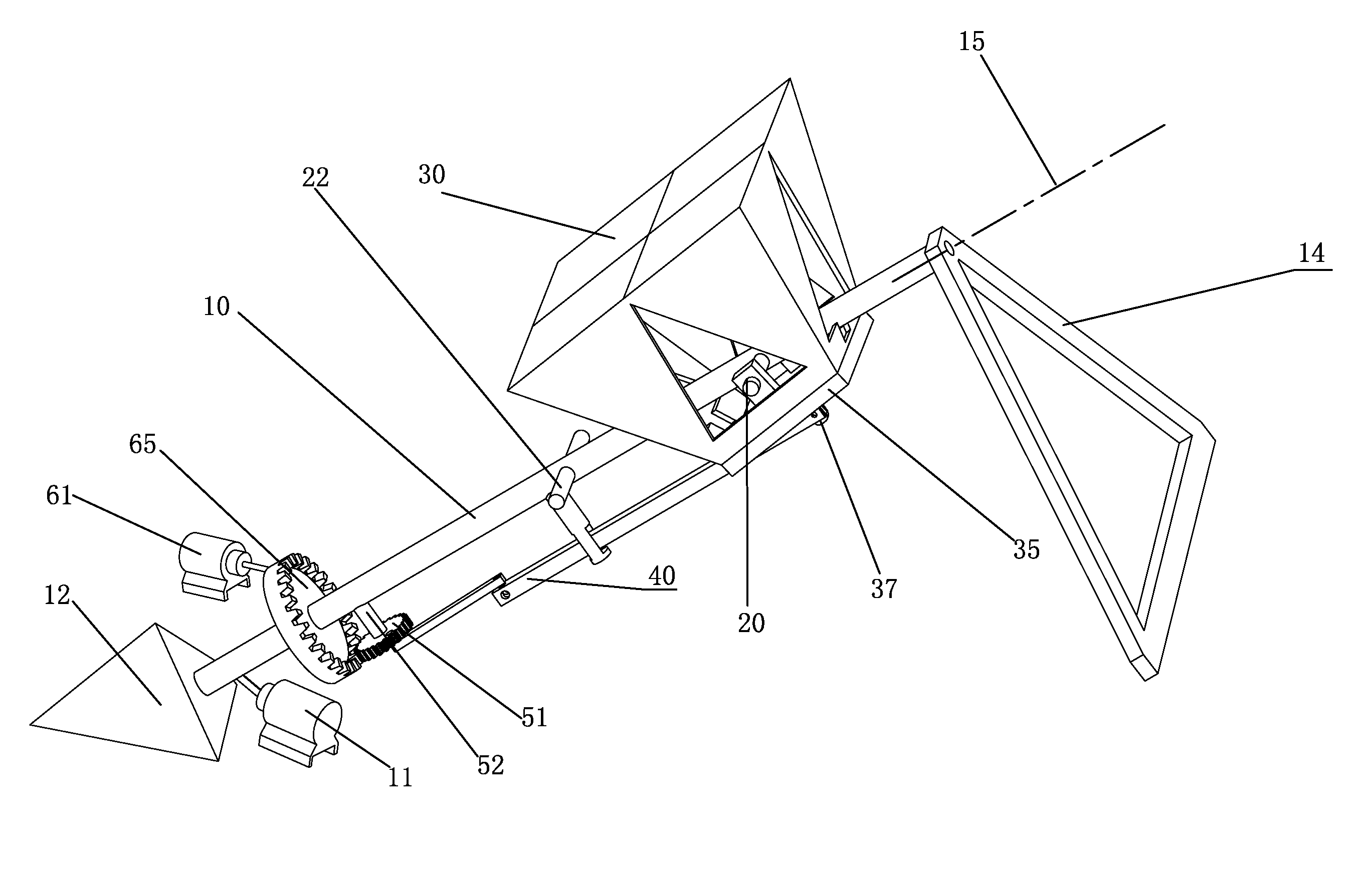
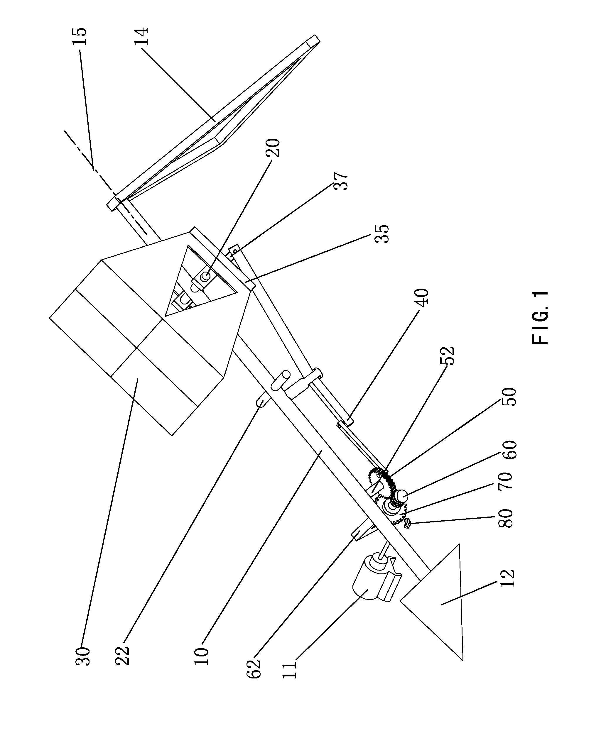
[0048]A 1-axis polar solar tracker is shown in FIG. 1, a rotatable shaft 10 is installed between a lower mount 12 and an upper support 14. Both 12 and 14 are fixed on the ground, and are installed in such a way that the shaft 10 can rotate along axis 15, which is essentially parallel to the celestial rotation axis of the Earth. Crossbars 20 and 22 are rigidly attached to the rotatable shaft 10, and the crossbars 20 and 22 are perpendicular to the rotatable shaft 10. There are more support beams 52 and 62 rigidly attached to the rotatable shaft 10. Solar energy collector 30 is mounted on the crossbar 20 and it could rotate around the crossbar 20 for at least ±23½°, which defines the declination angle. If we establish xyz coordinates here, center line of the shaft 10 as y-axis, center line of the crossbar 20 as x-axis, then we clearly know the z-axis is perpendicular to both x and y. the angle between the normal of the solar energy collector surface and the z-axis is the declination a...


PUM


Abstract

A one-axis sun position tracking device with its rotation axis parallel to the rotation axis of the Earth, rotates perpetually at a constant speed in the opposite direction of the Earth's rotation. This device comprises a shaft that is aligned to the Earth's polar axis, one or more crossbars are rigidly attached to and perpendicular to the shaft, solar energy collectors are mounted on the crossbar and could rotate around the crossbar that defines declination angle. A self-latched declination angle adjustment mechanism keeps the declination angle constant at most of time. A drive mechanism keeps this solar tracker to rotate perpetually. An automatic and abrupt declination angle change will keep the declination angle updated to correct value each day. A similarly configured two-axis tracker that continuously updates its declination angle by a mechanism derived from a differential coaxial rotation. Two independent driving mechanisms control the speed and/or duration of the two coaxial rotations, and are programmed to eliminate all tracking errors from various sources.

Description

CROSS-REFERENCE TO RELATED APPLICATION[0001]This application claims the benefit of provisional application Ser. No. 61 / 269,462, filed 2009 Jun. 26 by the present inventor.FEDERALLY SPONSORED RESEARCH[0002]Not applicableSEQUENCE LISTING[0003]NoneBACKGROUND[0004]1. Field[0005]This invention relates to solar energy collections, specifically to sun position tracking that is used in sunlight concentration and collection.[0006]2. Prior Art[0007]Sun position tracking is very important to solar energy collection, especially for solar concentrators. Different implementations have been invented, they could be categorized as 1-axis tracking and 2-axis tracking. 1-axis tracking is simple, however, it is commonly believed that 1-axis tracking has a poor tracking capability, that is not true in a special case; 2-axis tracking can have a very good tracking accuracy, however, it is usually very complicated because of the coupled rotation of 2-axis.[0008]Most 2-axis tracking methods are using local ...

Claims


Application Information

Patent Timeline
IPC IPC(8): F24J2/40F24J2/38F24S50/20
CPCF24J2/5413F24J2/5427F24J2002/5462H02S20/00G05D3/105Y02E10/47Y02E10/50F24J2002/5472H02S20/30F24S30/428F24S2030/134F24S30/458F24S2030/137
Inventor CHEN, DATONG
Owner CHEN DATONG
Why Eureka
Try Eureka